Chromalox UB-752D Identifikasi Suku Cadang Pemasangan, Pengoperasian, dan Pembaruan
Jelajahi secara online atau unduh pdf Identifikasi Suku Cadang Pemasangan, Pengoperasian, dan Pembaruan untuk Pemanas Chromalox UB-752D. Chromalox UB-752D 6 halaman. Forced-air heaters
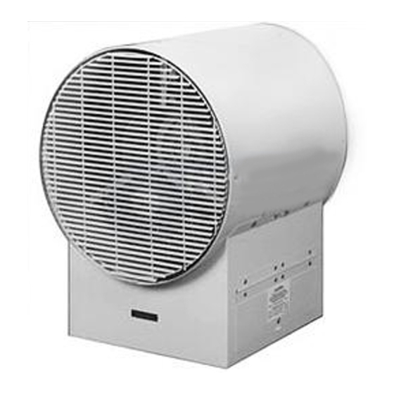
RENEWAL PARTS IDENTIFICATION
Dimensions —
11-5/8"
7-9/16"
Rubber Feet Provided for
Wall Mount Units Only.
WARNING: Hazard of Electric Shock. Disconnect all
power before installing heater.
Note: These heaters are designed for wall or ceiling mounting
only. Other modes of mounting voids factory warranty.
1. Height above floor
A. In areas where ceiling height is more than 12 feet, recom-
mended mounting height is approximately 10 feet to under-
side of heater.
B. For ceiling heights of 12 feet or less, maximum mounting
height is determined by use of ceiling mounting brackets
offered for these heaters. Minimum spacing to ceiling is 3"
(see Figure 2).
®
© 2010 Chromalox
, Inc.
Installation, Operation
and
Forced-Air Heaters
13-5/8"
17-3/16"
8-7/8"
7/8" and 1-13/32"
Dia. Holes in Rear
Figure 1
Mounting UB using ceiling
mounting brackets*
Specifications —
Model
UB-502D
UB-502D-R
UB-752D
UB-752D-R
‡ Model Numbers with suffix "T" added (480 volts only) are equipped with a transformer, 480V Primary — 120/240V Secondary.
‡ Model Numbers with suffix "R" added are equipped with a relay.
UB-502D and UB-752D
For Lower Height
from Ceiling:
Customer to add
Extension Strap.
8"
11-7/8"
6"
7'-0" Min. Height
Above Floor
Voltage and Phase
120 (1ø); 208, 240 or 480 (1ø or 3ø)
208, 240 or 480 (1ø or 3ø)
120 (1ø); 208, 240 or 480 (1ø or 3ø)
208, 240 (3ø); 480 (1ø or 3ø)
MOUNTING
C. In either case, minimum mounting height is 7 feet from
floor to bottom of heater. (See Figures 1 and 2.)
2. Spacing to adjacent walls
A. Rear of case to back wall 4-7/8" minimum (see Figure 2).
B. Side of case to side wall 6" minimum (see Figure 2).
3. If two or more units are operated in the same enclosed space,
their discharges should be directed to aid in development of
mass air movement for uniform heat dispersal.
4. Controlling thermostats to individual heaters should be
mounted at shoulder height on inside walls or columns.
SERVICE REFERENCE
4
DIVISION
SECTION
SALES
(Supersedes PF416-12)
REFERENCE
JULY, 2002
DATE
Ceiling Line
3"
Back
Wall
4-7/8"
Mounting
Holes
Center
8"
6"
15-9/16"
Figure 2
Mounting UB using wall
mounting brackets*
*Wall and/or Ceiling Mounting Brackets are
available as an accessory option — Contact
local sales representative.
Horizontal
kW
Air Discharge
(Ft.)
5
12.5
5
12.5
7.5
13
7.5
13
UB
PF416-13
161-048444-001
6" Min. Spacing to
Adjacent Wall
Wall
7'-0" Min. Height
Above Floor