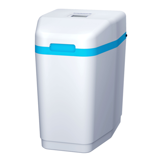
AQUAPHOR S550 P1 Panduan Pengoperasian - Halaman 11
Jelajahi secara online atau unduh pdf Panduan Pengoperasian untuk Dispenser Air AQUAPHOR S550 P1. AQUAPHOR S550 P1 20 halaman.

Figure 6
or other suitable waste water outlet. This pipe is not
included with the softener.
• Removal of excess water through the overflow line oc-
curs by gravity. Make sure the overflow line terminates
at a drain that is at least 8 cm below the edge of the
overflow fitting. Provide an air gap of at least 5 cm.
• It is not allowed to bend the outlet tube of the over-
flow line and lift it in height.
ATTENTION! The overflow line is part of the emergency
leak protection system. In its absence, in case of mal-
function of the softener and overflow of the brine tank,
water leakage is possible.
Step 4 Connect the drain line
The drain line is designed to drain water during regener-
ation.
• Connect the drain line to the drain port (see fig. 7) us-
ing the 5/8" ID ( ~ 16mm) flexible hose supplied with
the softener. Reducing the diameter is not allowed.
• Run a drain line to a drain, washing machine drain, or
other suitable sewage outlet. Provide an air gap of at
least5 cm between the drain line and the maximum fill
level of the wastewater receiver in order to prevent
backflow.
• The drainage line must be laid in such a way that the
distance to the drain is minimal. The drainage line can
Figure 7
Gravity overflow
connection
• The drain line may be extended with a pipe or hose
• The drainage line should not have kinks, creases,
ATTENTION! It is not allowed to combine drainage
(pressure) and overflow (gravity) lines by means of
tees, etc.
ATTENTION! During the regeneration process, small
solid particles may appear in the drain line, which does
not indicate a malfunction of the softener.
Step 5. Flushing the water supply
• Make sure the softener valve is in the "Bypass" posi-
• Open the nearest cold water faucet and flush the pipes
NOTE: When the softener is in Bypass mode, the water
is not treated.
Step 6. Make sure the connections are tight
Close all outlet taps to pressurize the system.
Check all lines and connections for leaks. If a leak is found:
a) turn off the water supply;
b) fix all leaks;
c) turn on the water supply.
Slowly move the valve to the "Service" position (see fig. 1),
slowly, to avoid water hammer, fill the softener.
Open the nearest cold water faucet to bleed air from the
system. When water comes out of the faucet without air,
close the faucet and check for leaks.
Step 7. Connecting the controller and power supply
NOTE: Make sure the controller is securely attached to
the three latches on top of the valve.
Connect to the back of the controller:
• flow sensor connector (fig. 8),
• motor connector,
Figure 8
Sensor wire
be raised to a height of up to 1.5 m above the drain
hole of the device, while the pressure in the water
supply must be at least 0.275 MPa (2.75 bar).
of at least 3/4".
twists or other damages that restrict the flow of water.
tion (see fig. 1) Turn on the water supply.
of solder flux residue and other foreign material.
Motor wire
Power cord
11
