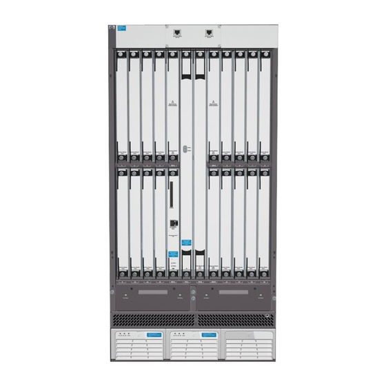
HP ProCurve 8116fl Petunjuk Pembongkaran Akhir Masa Pakai Produk - Halaman 2
Jelajahi secara online atau unduh pdf Petunjuk Pembongkaran Akhir Masa Pakai Produk untuk Beralih HP ProCurve 8116fl. HP ProCurve 8116fl 9 halaman. Redundant switch fabric module
Juga untuk HP ProCurve 8116fl: Lembar data (6 halaman), Petunjuk Pembongkaran Akhir Masa Pakai Produk (4 halaman)

2.0 Tools Required
List the type and size of the tools that would typically be used to disassemble the product to a point where components
and materials requiring selective treatment can be removed.
Tool Description
Philips screw driver
Hex Nut driver.
3.0 Product Disassembly Process
3.1 List the basic steps that should typically be followed to remove components and materials requiring selective treatment:
1.
Uninstall the Console module from the front top center of chassis by removing 4 of the screws as shown in picture 1.
2. Detach the cable connecting to the Console Module. Refer to Picture 2 for more details.
3. Remove the screws securing the bulkhead to the PCA of the console module.
4. Separate the PCA and the bulkhead.
5. Place the chassis assembly upright and remove screws in the back cover (22 per for 8slot and 30per for 16slot) and
remove the cover. Refer to Picture 3 for more details.
6. Remove the hex nuts securing the bulk capacitor to power cables. Refer to Picture 4 for more details.
7. Remove the rest of the hex nut securing the power cables to the backplane. Refer to Picture 5 for more details.
8. Detach the Console cable from the backplane. Refer to Picture 6 for more details.
9. Remove the screws (27per for 8slot and 51 per for 16slot) securing the backplane to the chassis. Refer to Picture 7 for
more details.
10. Separate the backplane, power cables, console cables and console module.
11. To remove the power shelf from the chassis. Place the chassis on a workbench facing up.
12. Remove the screws (8per) securing the power supply tray to the power shelf. Refer to picture 8 for more details
13. Push the tray up so as to release the tabs that are hooked into the slot located at the bottom of the chassis. Refer to
Picture 9 for more details
14. Separate chassis,power shelf, power supply tray.
15. To dismantle the cables within the power shelf, remove ground cable (5070-0171). Refer to picture 10 for more details.
16. Unplug the cables connecting the AC receptacles. Remove the screws (6 per) securing receptacles to the chassis.
Refer to Picture 10 for more details.
17. Unplug the Alarm cable (RST33-054-01). Refer to Picture 10 for more details.
18. Unplug the 3 ground wires (RST5092-1669) from the 3 AC Receptacles (RST9135-5690).
19. To separate the ground wires, remove the nut as shown in Figure 8a of Picture 9.
20. Remove the centre bracket together with cables from the power shelf chassis (RST5069-8640).
21. Remove all the screws and washers securing the cables to the mid-plane assembly and the centre bracket. Refer to
Picture 11 for more details.
22. Unplug cables (RST5070-1577).
23. Remove the screws and nuts securing the 3 AC receptacles that are secured to the centre bracket.
24. Remove the mid plane assembly from the centre bracket. Refer to Picture 11 for more details.
25. Separate mid-plane assembly, cables, centre bracket, AC receptacles, screws, washers, nuts.
26.
27.
28.
29.
30.
3.2 Optional Graphic. If the disassembly process is complex, insert a graphic illustration below to identify the items
contained in the product that require selective treatment (with descriptions and arrows identifying locations).
EL-MF877-00
Template Revision A
Tool Size (if
applicable)
# 2
3/8"
Page 2
