Alpha Marine Systems Alpha 3000 Panduan Instalasi dan Pengoperasian - Halaman 9
Jelajahi secara online atau unduh pdf Panduan Instalasi dan Pengoperasian untuk Sistem Autopilot Alpha Marine Systems Alpha 3000. Alpha Marine Systems Alpha 3000 16 halaman.

SECTION 3.1
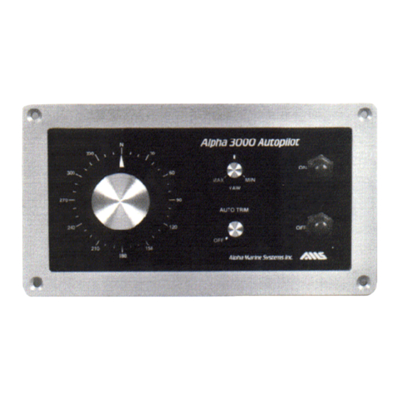
AUTOPILOT INSTALLATION INSTRUCTIONS
1. Make a two-way powered run, in each direction mark Center Helm position (this is
best done on a day with light winds and calm seas). Split the difference between these
two marks with a third mark. This is operational Center Helm position. Retain this
mark for use later in Drive Unit alignment.
2. Plan installation as outlined in the planning section, determine exact unit locations and
cable routing.
INITIAL DRIVE UNIT CENTERING
3. Your Drive Unit will be received in its full retracted position for shipping. To position
the Drive Unit at Center Helm for installation, temporarily connect the Drive Unit and
power to the Control Unit as shown in Fig. 3.1 for the selected extension sense.
WHEN SELECTING PROPER DRIVE UNIT CONN ECTION MAKE SURE MOTO R LEAD
CONNECTION IS IN AGREEMENT WITH RUDDER FEEDBACK CONNECTION.
Drive units may be installed in numerous configurations. However, the resulting steering
action when drive unit extends from Center position is to either steer the vessel to Port or
STBD. The Control Unit must know which way it is installed so it may steer correctly.
When the Drive Unit is installed to turn to PORT when it extends, wire Drive Unit to
Control Unit (Shown in Fig 3.1 PORT EXTENSION). When Drive Unit is installed to
turn to STBD when extended, install as shown in Fig. 3.1 STBD EXTENSION.
Set the YAW Control to Full CW and AUTO TRIM to OFF. Make sure the shipping
cord leads straight from the outer housing through the end fitting and back to the housing
with no twists. If not correct, rotate ram until you get a straight lead.
Misalignment will effect correct Center Helm positioning.
When correct, push Power On. The Drive Unit should extend so that 7.0" to 7 .5 " on
12" stroke drives of stainless steel ram exposed and to 9.5" to 10" on 18" stroke drives. .
This is the correct Center Helm position. Shut OFF the Power and use the extended
Drive Unit in subsequent installation steps.
If the Ram tries to retract shut OFF Power and correct wiring. If the Drive extends to
beyond Center
Position shut OFF Power and correct wiring.
4. Mount the Control Unit through a bulkhead on flush mounted units or in its bracket
for trunnion mounted unit.
**CAUTION**
**NOTE**
**CAUTION**
**CAUTION**
