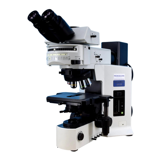
Olympus BX51M Petunjuk Manual - Halaman 20
Jelajahi secara online atau unduh pdf Petunjuk Manual untuk Mikroskop Olympus BX51M. Olympus BX51M 36 halaman. System metallurgical microscope

OBSERVATION METHODS (Using BX-RLA2)
}For the observation methods with the BX-URA2 universal illuminator, refer to its instruction manual.
4-1 Reflected Light Brightfield/Darkfield Observation
See "REFLECTED LIGHT BRIGHTFIELD/DARKFIELD OBSERVATION PROCEDURE" on page 5.
4-2 Reflected Light Nomarski DIC (Differential Interference Contrast) Observation
# The performance of polarizer may deteriorate when it has been exposed to light for a long period (about continu-
ous 2000 hours). If this happens, replace the polarizer.
# When performing sensitive color observation using the U-DICRH DIC slider, combine the U-POTP3 polarizer.
# When using the high-intensity light source, be sure to use the U-25L42 filter to prevent the polarizer from being
burnt.
ƒ
17
²
³
@
Fig. 29
...
|
Fig. 30
1
Setting the Analyzer and Polarizer
# In the current step, do not engage the DIC slider in the light path.
1. Bring the specimen in approximate focus using the 10X or 20X objective.
2. Remove the cover to enable installation of the U-AN360-3 analyzer. Then
put the analyzer @ in the insertion slot.
3. Insert the U-PO3 or U-POTP3 polarizer ² so that the surface with indica-
tion comes on the front, and engage the polarizer in the light path.
4. Rotate the analyzer rotating dial ³ to find the position where the field of
view is darkest.
}An approximate cross-Nicol position can be obtained by setting the in-
dex on the dial ³ on the outer side. Fine-adjust the dial by rotating it near
this position to find the position where the field of view is darkest.
Using the Coupling Plate (Fig. 30)
When the U-AN360-3 analyzer ƒ and U-PO3 or U-POTP3 polarizer ... are
coupled by using the coupling plate | provided with the polarizer and
tightening the clamping knobs on it, the analyzer and polarizer can be
engaged or disengaged in the light path together.
(Fig. 29)
