Olympus MX61 Panduan Perakitan - Halaman 15
Jelajahi secara online atau unduh pdf Panduan Perakitan untuk Mikroskop Olympus MX61. Olympus MX61 49 halaman. 200mm/300mm compatible semiconductor/fpd inspection microscopes
2-2 Detailed Assembly Procedures
!The system contains motorized parts. Do not plug in the power cord until all of the assembly procedures have
completed.
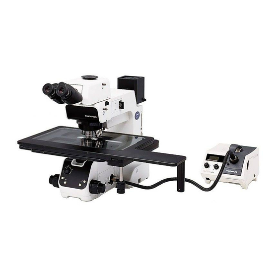
Fig. 4
@
Fig. 5
ƒ
Fig. 6
1
Attaching the Stage
1. Using the Allen wrench (3 mm), remove the transport clamping plate @
from the rear edge of the stage. (Fig. 5) The removed screws should be
used to clamp the stage when attaching it.
}With the MX-SIC6R2/SIC6A, the mounting screw holes are invisible un-
less the upper stage is displaced. It is therefore necessary to remove the
transport clamping plates from the front and rear of the stage.
# Two transport protection sheets are placed in the gaps of the MX-
²
SIC6A/SIC6R2/SIC8R stage. Be sure to remove them before using
the system.
2. While holding the stage so that the coarse adjustment grip and X-axis/
Y-axis knobs are on the right, gently place the stage on the stage holder
². Using the Allen screwdriver or Allen wrench, tighten the four screws
³
temporarily.
3. Remove the transport clamping plate(s) from the front ³ and side (MX-
SIC1412R2 only) | of the stage, move it to the rearmost position and,
after confirming that the stage and arm do not interfere with each other,
tighten the four screws firmly. (Fig. 5)
# The clutch and belt may stick together and prevent smooth operation
of the release function if the stage has not been moved for a long
|
time. If this phenomenon occurs, take the remedial action described
in page 22 in the instruction manual.
Attaching the Y-Stroke Limit Stopper (Fig. 6)
}When the MX-SIC1412R2 stage is used in transmitted light observation
(possible only when the MX-TILLA is used), it is required to attach this
stopper for limiting the Y-axis stroke to 10 inches in order to prevent
interference between the stage and the projected part of the condenser.
1. Place the stage upside down and remove both transport clamping plates.
2. Move the stage and insert the stopper, provided with the stage, into the
two stopper holes ƒ on the center stage.
3. Attach only the front transport clamping plate and then attach the stage.
Caution Before Transporting the Stage (Fig. 5)
Before transporting the stage, be sure to attach the transport clamping
plates @³| and package the stage carefully. Do not transport the stage
when it is attached to the microscope frame or inadequately packaged.
Otherwise, the stage will be damaged.
MX61/MX61L
(Figs. 4 & 5)
12