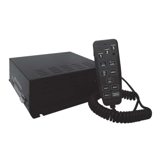
AXIXTECH SAF205H Panduan Instalasi dan Pengoperasian - Halaman 9
Jelajahi secara online atau unduh pdf Panduan Instalasi dan Pengoperasian untuk Penguat AXIXTECH SAF205H. AXIXTECH SAF205H 16 halaman. Electronic handheld siren

LIGHT CONTROL CONNECTIONS
Power – The power input for the light controls (the three LV switches and the four auxiliary
control switches) are separate from the power inputs for siren. This design helps prevent a
fault in one main circuit from affecting another main circuit.
Fuses/Breakers – Each light control output is fused and should be limited to 10 Amps.
Proper rated circuit breakers should be connected between the power source and light
control power inputs. Refer to "FUSE LOCATION" diagram for proper fuse location below.
WARNING: Improper circuit breakers or fuses can result in damage to the unit and/or vehicle.
FUSE LOCATION
10A FUSE
PROGRAMMING
Once the electrical connections are made and the power is available to the unit, each of the three
LV buttons and four auxiliary control buttons are ready to be programmed. The programming
mode is entered by changing the DIP switch.
Follow these steps to program the unit:
Get into program mode.
1. Turn unit on with enable input.
2. Enter the program mode by turning DIP-SW2-8 (PRG) switch on.
Set Auxiliary Control Buttons Operation (all LV buttons off)
1. With all LV buttons off, each auxiliary switch current operation program status is indicated
on each push button. See the table below for switch status definition.
2. Change button operation by momentarily pushing the auxiliary button.
LED showing
Red Steady
Red Flashing
Red off
NOTE: The Timed Momentary operation, typically used as a Gun Lock Timer, must begin
with push button 3. If push button 3 is programmed as timed momentary, only
then push button 2 may be programmed also as a timed momentary and so on.
(open siren top view)
AUXILIARY button setting
PUSH on / PUSH off (default)
MOMENTARY
TIMED MOMENTARY (10 seconds)
- 8 -
SAF205H Siren_v.1
