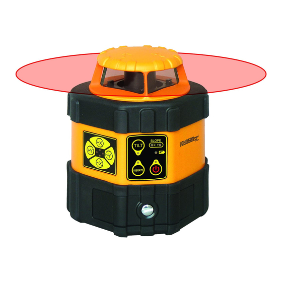
AccuLine 40-6537 Panduan Servis - Halaman 7
Jelajahi secara online atau unduh pdf Panduan Servis untuk Alat Ukur AccuLine 40-6537. AccuLine 40-6537 15 halaman. Auto-leveling rotating laser
Juga untuk AccuLine 40-6537: Buku Petunjuk (18 halaman)

3.1. Horizontal Mode Operation
In this mode of operation, the instrument is self-leveling, where by a major factor of accuracy is how well the leveling
compensator is balanced. Different types of errors require different methods of calibration. These errors are easily characterized
by placing the instrument on a flat surface following the guidelines below, and running the instrument with the rotating head
continuously rotating 360°.
3.1.1. Quantifying Accuracy Error
Establish the test set-up shown in the following illustration and confirm that it meets the following requirements:
1)
The debugging platform should be horizontal with a error less than 0.1°(6');
2)
The distance L from the center of the debugging clamp to the wall should be L≥10m;
3)
The accuracy of the reference marking is no less than 0.05mm/m;
4)
The adjacent-light ruler should be put within 0.3m (12") of the instrument (the zero position of the ruler should be located at
the same height as that of the laser line at the emitting hole).
Instrument for test (laser spinning 360° rotation)
Flat Surface (Test Stand)
1.
Place the instrument for test on the test stand (preconfigured from the illustration above) with handle facing the far target .
2.
Power the laser and function in full rotation mode (head rotates 360°)
3.
Note the errors in all four quadrants of the instrument as read on the far target (i.e. x axis A = 0° and B = 180°, y axis C = 90°
and 270°)
You should end up with 4 numbers
i. A (0°) =
ii. B (180°) = ______
iii. C (90°) = ______
iv. D (270°) = ______
4.
Since all of the errors are referenced against "0" on the far target, essentially the largest number from the data collected (A – D)
/ the distance should be equal to or less than the published specification for the product. If not, characterize the error and
determine method of calibration as defined by section 4.1.2 of this document.
Prepared By: Tim Wojo
Distance (L) >10m (33ft)
0
Near Target placed within 0.3m (12") of
instrument. Note that "0" of the target
corresponds to the height of laser line at the
aperature of the instrument.
_____
Revision - Date: 0 – 03232009
40-6537 Service Manual
Far Target placed on wall at least 10m (33ft) from Test
Stand, where "0" corresponds to them same height as
"0" on the target next to the aperature of the instrument.
Laser line
0
Reference Line (Known Height)
Target
Accuracy (A) = Difference between laser line
height and reference line height, divided by the
distance that the laser is from the wall (L)
Page 7 of 15
