Olympus BH-NRE Manual - Halaman 10
Jelajahi secara online atau unduh pdf Manual untuk Peralatan Laboratorium Olympus BH-NRE. Olympus BH-NRE 17 halaman. Modular revolving nosepiece
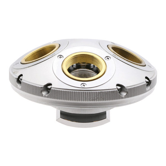
Figure 23 – Apply ring of fresh grease to stationary base
Reinstall Stationary Base into Revolving Turret
Hold the stationary base such that the center pivot is
facing downwards, and then lower the greased
stationary base into the recess of the revolving turret
(see
Figure
24).
Figure 24 – Reinstall stationary base into revolving turret
Reinstall the Perimeter Bearing Balls
Use tweezers to carefully set the 3/32" bearing balls
(there are 80 of them) into the grease ring (see
25), placing the bearing balls as close together as
possible as you proceed.
Figure 25 – Place the bearing balls into the ring of grease
Complete Teardown, Cleaning, and Reassembly of the Olympus BH-NRE Modular Revolving Nosepiece
Reinstall the Threaded Retaining Ring
Carefully engage the threads of the threaded retaining
ring with the threads in the revolving turret (see
26). Make sure the tooling holes are facing upwards.
Figure 26 – Engage the threaded retaining ring
Use a suitable lens spanner tool (item T3 of
with the pointed tips seated into a pair of opposing
tooling on the threaded retaining ring to carefully
tighten the threaded retaining ring
Figure
Figure 27 – Tighten the threaded retaining ring
While holding the stationary base in one hand, quickly
spin the revolving turret multiple times in both
directions with the other hand, to drive out any excess
grease from beneath the threaded retaining ring. Use
dry cotton swabs to remove any grease squeeze-out
(see
Figure
grease squeeze-out, otherwise the solvent may run into
the revolving turret mechanism and foul the grease
within. Repeat this step as necessary until no further
grease squeezes out when the revolving turret is spun.
2
Or use a center punch or nailset tool to snug the threaded retaining ring by
placing the tip of the tool into one of the four tooling holes and lightly
tapping the tool with a small hammer or mallet to drive the threaded
retaining ring clockwise.
2
(see
28). Do not use a solvent to clean this
Figure
Appendix
2)
Figure
27).
Page 10 of 17
Revision 3