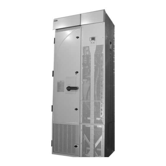
ABB ACS550 Series Panduan Tambahan Instalasi - Halaman 9
Jelajahi secara online atau unduh pdf Panduan Tambahan Instalasi untuk Pengontrol ABB ACS550 Series. ABB ACS550 Series 16 halaman. Drive it low voltage ac drives 150...550 hp
Juga untuk ABB ACS550 Series: Panduan Memulai Cepat (2 halaman), Panduan Memulai Cepat (2 halaman), Panduan Pengguna (14 halaman)

Installation Supplement for ACS550-U2 Drives
Maintenance
This section describes the procedure for separating the drive and extension
modules, which is required to provide service access to the drive module.
Safety
WARNING! Read "Safety" on the first pages of this manual before performing any
maintenance on the equipment. Ignoring the safety instructions can cause injury or
death. Note: There are parts carrying dangerous voltages near the OMIO board
when the drive is powered.
Separating the Drive and Extension Modules
The drive module is mounted on a trolley that straddles a pedestal. The following
procedure removes mechanical connections so that the drive module and trolley can
roll forward for service access.
1. Disconnect all power sources from the drive/
extension modules and wait at least 5 minutes for
internal capacitors to fully discharge.
2. Remove all front covers from the drive module.
3. Disconnect the control panel cable.
4. Remove the upper side plate from the drive module
if convenient.
5. Remove screws (if any) that fasten the drive module
to the wall.
6. Inside the pedestal, toward the rear are screws that
attach the drive bus bars to the pedestal bus bars.
The connections are staggered for easy access
using a wrench with an extension. Remove these
screws (6).
Torque when re-assembling:
• R7: M8 (5/16 in) screws, 15...22 Nm (11...16 lb
ft)
• R8: M10 (3/8 in) screws, 30...44 Nm (22...32 lb
ft)
Warning! Be careful not to drop screws inside the
pedestal. Loose metal pieces inside the unit may
cause damage.
R7
6
Maintenance
9
5
