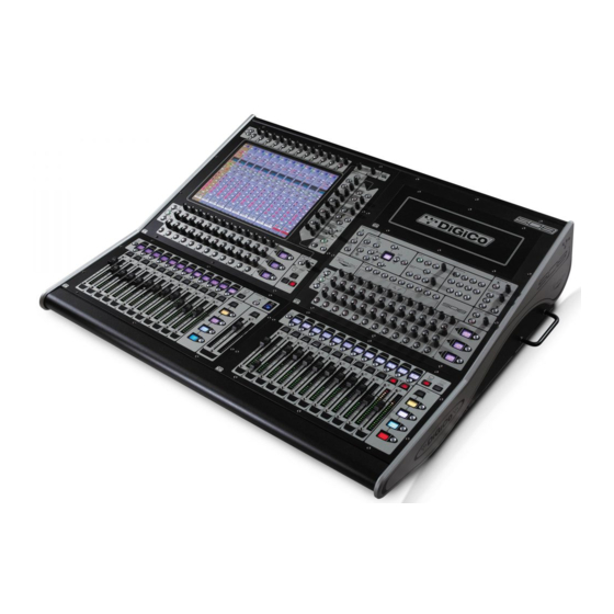
digico SD8 Petunjuk Keselamatan, Panduan Penyiapan & Pemasangan - Halaman 10
Jelajahi secara online atau unduh pdf Petunjuk Keselamatan, Panduan Penyiapan & Pemasangan untuk Mixer Musik digico SD8. digico SD8 13 halaman. Replacing and cleaning faders
Juga untuk digico SD8: Manual (9 halaman)

Setup & Installation Manual
Rack Modules ................................................................................
There are different Rack Modules for interfacing to different digital and analogue devices. Each Rack Module carries eight channels
of audio.
Rack Module Inputs and Outputs ................................................
The modules fall into two broad groups - those which carry only inputs or outputs, and those which carry both input and output
signals. Output modules must be installed in Output slots, while Input and I/O modules must be installed in Input slots.
Example Installation .....................................................................
This shows a rack, with 48 Mic inputs and 8 line outputs.
Rack Module Connections ...........................................................
Audio connections to the Rack Modules are made using appropriate connectors for the type of module. See the Connector Tables
for a list of the different connectors used in the Rack Modules.
MADI Cabling Considerations .....................................................
The MADI (Multichannel Audio Digital Interface) standard was devised to operate using standard video coaxial cable installations.
For short cable runs of up to 5m, any good quality video cable should be sufficient. The maximum length of a MADI cable
connection between the Worksurface and a Rack Unit is 100m nominal.
MADI uses 75ohm cable. 50ohm cable such as that used for computer networks is not acceptable.
The bandwidth of a MADI signal is such that care must be exercised when installing long cable runs. In general, for maximum
length cable runs, a high performance video cable such as RG59/U cable should be used. If in doubt about the suitability of a
particular cable type, a sample of the correct length can be tested with the system prior to installation to prove its suitability.
The MADI signal should NEVER be routed via video distribution amplifier or switching arrangements, and any form of plug and
socket patching of MADI signals should be avoided if at all possible. There should be NO common earth connection with other
systems (including video) made via the sleeves of MADI cables.
Detailed MADI cable specification and considerations are detailed in Digico Technical Bulletin 106
Synchronisation Connections .....................................................
When the SD8 is used with only analogue signals connected to both inputs and outputs synchronisation does not
need to be considered. In this case the mixer is run from its own internal master clock.
There are, in fact, two separate synchronisation systems which use different connections - the Sample Word Clock (or Digital
Sync) and the Timecode system (not usually used for conventional live sound applications).
The issues surrounding synchronisation in a digital system are complex, and do not fall within the scope of this manual, but this
section gives a basic description of the console's different sync inputs and outputs.
Timecode Connections ................................................................
(not Normally used on the SD8 for conventional Live use)
The console cannot be slaved to external timecode but it can generate it's own timecode outputs via the software Snapshot/
Timing panel. All timecode connections are made via the Worksurface rear panel, which has input and output connections for MIDI
timecode and Sony 9-pin (RS422). The MIDI and 9-pin systems also provide Machine Control inputs and outputs.
Page 10
