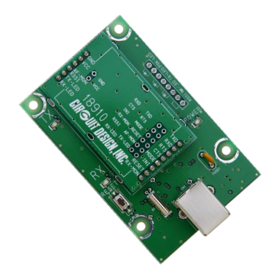
CIRCUIT DESIGN MU4-USBIF Panduan Pengoperasian - Halaman 10
Jelajahi secara online atau unduh pdf Panduan Pengoperasian untuk Antarmuka USB CIRCUIT DESIGN MU4-USBIF. CIRCUIT DESIGN MU4-USBIF 18 halaman. Embedded low power radio modem usb interface board

* When making your circuit board based on this circuit diagram, pay due attention to high frequency noise around the USB chip and from the interface.
1. Exercise caution in placement of the MU-4 and USB chip. In addition, there are cases where shielding is necessary around the chip.
2. Add a noise filter to the USB interface signal wire.
3. Ensure a sufficiently large ground pattern for the MU-4. In addition, provide shielding for the signal wire too.
OG_MU4-USBIF_v10e
2.6 Circuit Diagram
9
OPERATION GUIDE
MU-4
Circuit Design, Inc.
