CIRCUIT DESIGN MU4-USBIF Panduan Pengoperasian - Halaman 6
Jelajahi secara online atau unduh pdf Panduan Pengoperasian untuk Antarmuka USB CIRCUIT DESIGN MU4-USBIF. CIRCUIT DESIGN MU4-USBIF 18 halaman. Embedded low power radio modem usb interface board
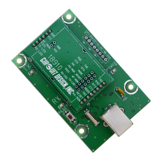
Chapter 2 The MU4-USB (MU-4 + MU4-USBIF)
[06]Conversion board
[04]TX-LED
[03]RX-LED
[02]Initialize button
[01]USB-B type receptacle
[01] USB-B receptacle: For connecting the double shield USB cable (USB 2.0 High Speed).
[02] Initialize button: Resets the MU-4 mounted on the MU4-USB to the factory default settings. Follow the
procedure below.
1. Turn on the power (connect the USB cable) while pressing the initialize button.
2. Release the initialize button and after turning off the power (remove the USB cable), turn the power again
(connect the USB cable) after a while (approx. 5 seconds).
[03] RX-LED: On when data is received.
[04] TX-LED: On when data is transmitted.
[05] MU-4: A low power serial data transmission modem.
[06] Conversion board: A board making it possible to fit the pins of the MU-4 into the USB board.
[07] λ/4 lead antenna: A λ/4 long lead antenna. (ANT-LEA-01, ANT-RIG-01-R)
[08] Mounting holes: 3Φ holes for mounting
[09] Power LED: The LED comes on when the USB cable is connected.
OG_MU4-USBIF_v10e
2.1 Part Names and Functions
[05]MU-4
[07]λ/4 lead antenna
5
OPERATION GUIDE
[08]4-mounting holes
[09]Power LED
Circuit Design, Inc.