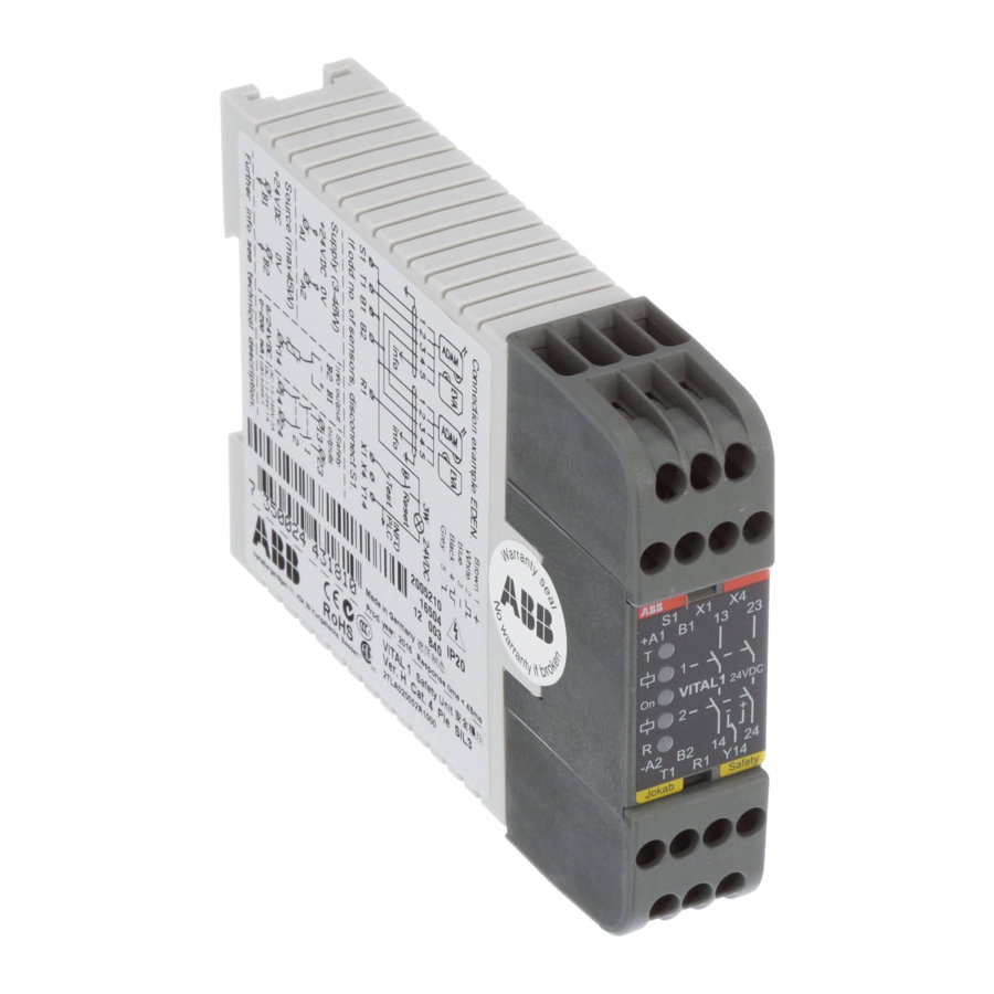
ABB vital 1 Manual - Halaman 11
Jelajahi secara online atau unduh pdf Manual untuk Pengontrol ABB vital 1. ABB vital 1 14 halaman. Safety controller
Juga untuk ABB vital 1: Manual Petunjuk Asli (20 halaman)

Vital 3
Vital 3 is a safety controller that combines functionality with
the quick and easy installation of safety sensors. With two
safe input functions and two different output groups, Vital 3
offers the capability to exclusively control smaller machine
safety systems that would otherwise have required a pro-
grammable controller or multiple safety relays. How the two
output groups are controlled by the input functions depends
on which of the three operating modes is selected (see Selec-
tion of operating mode).
5:16
Input function 1:
A two-channel safety circuit designed for opening contacts,
e.g. two-channel emergency stop or ABB Jokab Safety's
safety switch JSNY5. One channel is fed with the dynamic
signal and the other with static +24 VDC.
Input function 2:
A dynamic safety circuit where ABB Jokab Safety's safety
sensors Eden, Tina and Spot can easily be connected in se-
ries. Up to 12 Eden or Tina devices can be connected in
series per input function.
Output group 1:
A safe relay output in a duplicated series and a safe transistor
output with output voltage of -24 VDC.
Output group 2:
A safe relay output in a duplicated series and a safe transistor
output with output voltage of -24 VDC. In addition, output
group 2 contains a non-safe transistor output with output
voltage of +24 VDC, intended for information. The output
group can have time delay from 0 to 1.5 s.
Selection of operating modes
Vital 3 can be configured to operate in one of three operat-
ing modes M1, M2 or M3. The selection of operating modes
is done by connecting one of the terminals M1, M2 or M3
to +24 V.
ABB
