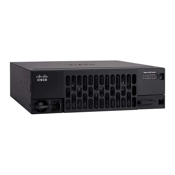
Cisco 4500-M Panduan Peningkatan - Halaman 5
Jelajahi secara online atau unduh pdf Panduan Peningkatan untuk Beralih Cisco 4500-M. Cisco 4500-M 24 halaman. Upgrading memory
Juga untuk Cisco 4500-M: Panduan Instalasi (18 halaman), Manual Penggantian (16 halaman)

Always follow ESD prevention procedures when removing and replacing cards. Ensure that the
chassis is electrically connected to earth ground. Wear an ESD-preventive wrist strap, ensuring that
it makes good skin contact. Connect the clip to an unpainted surface of the chassis frame to safely
channel unwanted ESD voltages to ground. To properly guard against ESD damage and shocks, the
wrist strap and cord must operate effectively.
If no wrist strap is available, ground yourself by touching the metal part of the chassis.
Required Tools
The following tools are required to remove and upgrade main, shared, Flash, and ROM monitor
memory.
•
ESD cord and wrist strap
•
Number 1 and Number 2 Phillips screwdrivers
In addition, the ROM monitor device upgrade requires the following:
•
EPROM removal tool or small flat-blade screwdriver
Proceed to the next section, "Accessing the Internal Components of the Router."
Accessing the Internal Components of the Router
You must open the router chassis to gain access to the router's internal components: the network
processor modules, boot ROMs, and jumpers.
Refer to the previous section, "Required Tools," for the tools needed for the following procedures.
Warning
with telephone-network voltages.
Warning
activity.
Warning
power switch, line voltages are present within the power supply even when the power switch is off
and the power cord is connected. For systems without a power switch, line voltages are present
within the power supply when the power cord is connected.
Removing the Component Tray Procedure
Some Cisco 4000 series routers have a safety latch tab on the chassis that affects removing the
component tray. (See Figure 3 and Figure 4.)
If you have a chassis with a safety latch tab, follow the procedure in the next section "Removing the
Component Tray from a Chassis with a Safety Latch."
If you have a chassis without a safety latch tab, follow the procedure in the section "Removing the
Component Tray from a Chassis without a Safety Latch."
Before opening the chassis, disconnect the telephone-network cables to avoid contact
Do not work on the system or connect or disconnect cables during periods of lightning
Do not touch the power supply when the power cord is connected. For systems with a
Upgrading Cisco 4500, Cisco 4500-M, Cisco 4700, and Cisco 4700-M Memory
Required Tools
5
