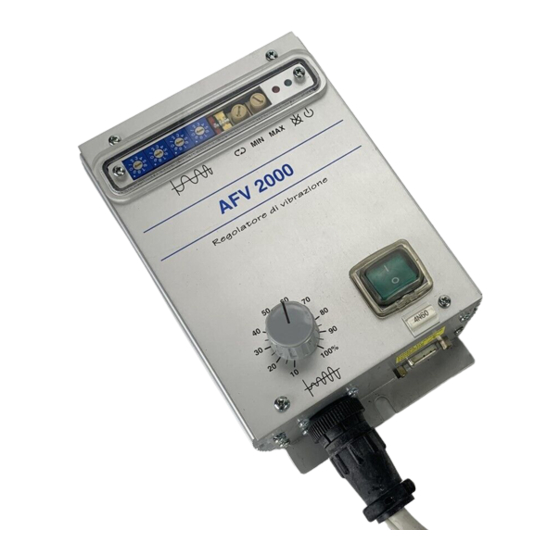
DIGISYSTEM APS20201 Buku Petunjuk - Halaman 9
Jelajahi secara online atau unduh pdf Buku Petunjuk untuk Catu Daya DIGISYSTEM APS20201. DIGISYSTEM APS20201 9 halaman. Variable frequency vibrators power supply

OPTIONS WIRING TABLE (M2)
REF.
SIGNAL DESCRIPTION
M2-8 Voltage reference (0-5v)
M2-7 Potentiometer cursor
M2-6 Potentiometer minimum
M2-5 Potentiometer maximum
M2-4 0V insulated for remote commands
M2-3 Remote start command (PNP or NPN)
M2-2 Output power supply OK (PNP)
M2-1 +18V insulated for remote commands
If voltage reference is coming from potentiometer 10K located on front panel, the
switch SW3 (yellow) must be ON (lever up);
The power supply is delivered with this switch on.
If voltage reference is coming from external voltage generator, the switch SW3 (yellow)
must be OFF (lever down) connect 0V at pin 6 and reference at pin 8.
If voltage reference is coming from external potentiometer 10K, the switch SW3
(yellow) must be OFF (lever down), the potentiometer sliding contact must be connected to
pin 8, the CW to pin 5 and the CCW to pin 6.
A switch (SW2 red) on front panel selects automatic or remote start/stop; the switch
ON selects start at power-on, the switch OFF enables start from external command. The
power supply is delivered with this switch ON.
The start-stop control with one external sensor (photocell or other type of sensor) is
available a supply (18 V 50 mA not stabilized).
PNP Sensor: connect supply of sensor between pins 1 (
sensor at pin 3.
NPN Sensor: connect supply of sensor between pins 1 (
sensor at pin 3 and change position of jumper H4 from P to N; H4 is located inside the box,
see opening instructions.
Inverter OK: for remote check of the power supply is available a PNP (18V 20mA) signal
at pin 2; pin 4 is 0V.
POT.
PLC
Ref.(0÷5V)
Cursor
Ccw
0V Plc
Cw
No connect.
) and 4 (
+18V
) and 4 (
+18V
9
Wire mmq
0,5
0,5
0,5
0,5
0,5
0,5
0,5
0,5
), connect signal of
0V
), connect signal of
0V
