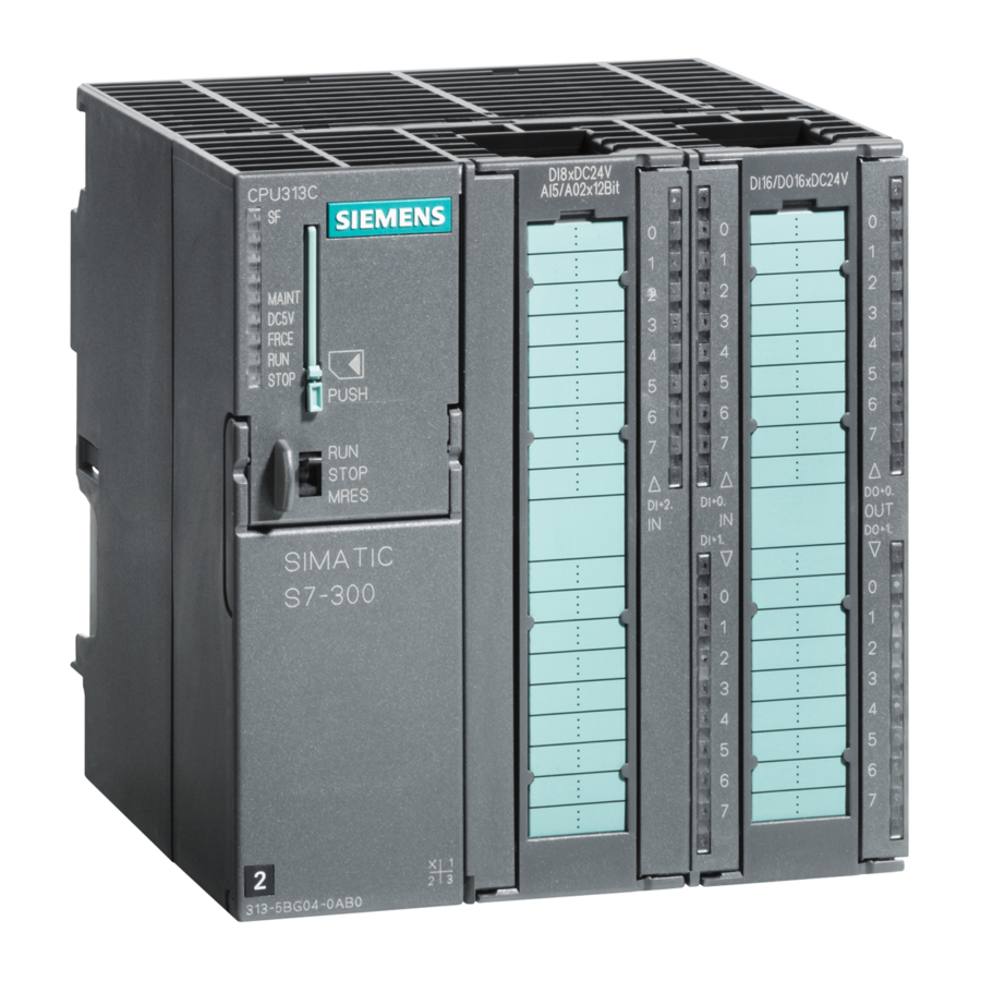
Stage
1
Open the front doors of the DI and DO.
2
Position the front connectors so that you can wire them:
To do this, push a front connector into both the DI and the DO until it snaps into position. The front con-
nector still sticks out of the module in this position. A wired front connector has no contact with the module
in the wiring position.
3
Strip 6 mm from the wire ends you want to insert in the front connector and attach appropriate wire-end
ferrules.
4
Wire the front connector of the DI as follows:
Terminal 1: L+ of the PS; terminal 13: switch 1; terminal 14: switch 2; terminal 20: M of the PS.
5
Wire the front connector of the DO as follows:
Terminals 1 and 11: L+ of the PS; terminal 20: M of the PS.
6
Wire the free wire ends of the switches to L+ of the PS.
7
Lead the wires downward out of the front connectors.
8
Press the release button of the front connector on the upper part of the module and at the same time push
the front connector into the module until the release button jumps back into its original position.
9
Close the front doors of the DI, DO and PS.
Step 3: Commissioning the Hardware
Stage
1
Connect the programming device to the CPU with the programming device cable. Make sure that the ter-
minating resistors are inserted in the connectors. Close the front door of the CPU and put the mode selec-
tor switch to STOP .
2
Connect the power cable to the network and switch on
the PS 307 power supply module.
3
Insert the buffer battery:
– Insert the buffer battery connector into the cor-
responding socket in the battery compartment
of the CPU. The groove on the connector must
be facing left.
– Insert the buffer battery in the battery compart-
ment of the CPU.
– Close the front door of the CPU.
4
Raise the programming device and start SIMATIC Ma-
nager on the Windows desktop.
5
Carry out a memory reset in the CPU as follows:
– Turn the mode selector switch to MRES . Keep the mode selector switch in this position until the
STOP LED comes on for the second time and stays on (this takes 3 sec.).
– Within 3 sec. you must turn the mode selector switch back to MRES . The STOP LED starts to flash
rapidly and the CPU carries out a memory reset. When the STOP LED comes on permanently
again, the CPU has completed the memory reset.
6
Activate switch 1.
7
Activate switch 2.
S7-300 Programmable Controller, Getting Started, First Steps for Installation and Commissioning
A5E00069340 01 // 04/2000
Wiring the Front Connectors of the DI and DO
What to Do
Result
The DC24V LED lights up on the PS.
All the LEDs on the CPU come on briefly; the SF
LED, the BATF LED and the DC5V LED remain
on. The STOP LED flashes rapidly for 3 sec. and
then remains on.
The BATF LED goes off followed shortly after-
wards by the SF LED.
A SIMATIC Manager window appears.
The E0.1 LED on the DI comes on. No LEDs
light up on the DO.
Die E0.2 LED on the DI comes on. No LEDs light
up on the DO.
5

