Siemens SINAMICS G120 Deskripsi Aplikasi - Halaman 13

Jelajahi secara online atau unduh pdf Deskripsi Aplikasi untuk Peralatan Industri Siemens SINAMICS G120. Siemens SINAMICS G120 50 halaman. Using blocksize converters in marine applications
Juga untuk Siemens SINAMICS G120: Memulai (46 halaman), Panduan Petunjuk Pengoperasian (32 halaman), Memulai (30 halaman), Petunjuk Pemasangan Perangkat Keras (2 halaman), Petunjuk Pemasangan dan Panduan Pemilik (2 halaman), Petunjuk Instalasi (2 halaman), Petunjuk Instalasi (2 halaman), Petunjuk Pengoperasian yang Ringkas (32 halaman), Manual (42 halaman), Memulai (50 halaman), Panduan Perangkat (34 halaman), Panduan Pemasangan Cepat (2 halaman), Petunjuk Pengoperasian yang Ringkas (2 halaman), Manual (31 halaman), Manual Aplikasi (34 halaman), Petunjuk Pengoperasian yang Ringkas (2 halaman), Petunjuk Pengoperasian yang Ringkas (2 halaman)
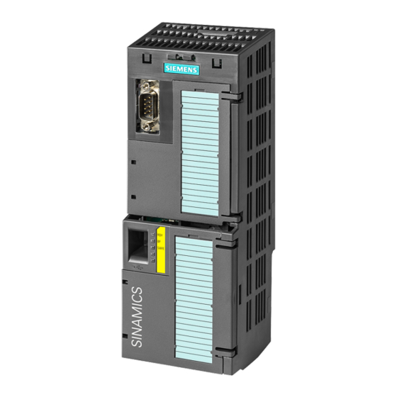
Siemens SINAMICS G120 Deskripsi Aplikasi
3 Principle of Operation
3.2 Interaction of motion control instructions and technology objects
Only an appropriate chronological order of the calls of the motion control
instructions in the control program of the SIAMTIC S7-1500 allows you to use the
TO in a technologically useful way.
Therefore, it is recommended to use a sequencer in the user program from which
the motion control instructions according to the PLCopen standard are called.
3.2.2

Technology data blocks

After generating the technology objects, technology data blocks are automatically
created. The TO status and more TO-typical information is entered in these blocks;
for an axis, this is, for example, the current position
The technology data block can be accessed like a normal data block.
3.2.3

Principle of motion control instructions

Figure 3-2
Basically, all motion control instructions work on the following principle:
The Axis input specifies to which TO and therefore to which axis the motion
control instruction is to be sent.
A rising edge at the Execute input triggers the job. The job type depends on
the motion control instructions used.
The status outputs of the FB (Busy, Done, CommandAborted and Error)
display the job status.
While a job is active, the Busy output parameter displays the value TRUE;
when the job is complete, Busy displays the value FALSE.
The other output parameters display the status for at least one cycle. While
the Execute input parameter is set to TRUE, these status messages are
displayed on a latching basis.
4
Positioning axes only
SINAMICS G120 as a Speed Axis on the S7-1500
V1.0a, Entry ID: 78788716
While the Execute input is set to TRUE, the job status is displayed at
the status outputs of the FB (Busy, Done, CommandAborted and
Error).
If the Execute input parameter is set to FALSE while the job is not yet
complete (Busy = TRUE), the Done output (or Error or
CommandAborted) will be set to TRUE for only one cycle once the job
is complete!
4
and velocity.
13