Siemens SINAMICS G120P Panduan Petunjuk Pengoperasian - Halaman 17

Jelajahi secara online atau unduh pdf Panduan Petunjuk Pengoperasian untuk Peralatan Industri Siemens SINAMICS G120P. Siemens SINAMICS G120P 24 halaman. Line reactors for power modules pm330
Juga untuk Siemens SINAMICS G120P: Panduan Petunjuk Pengoperasian (28 halaman), Panduan Petunjuk Pengoperasian (26 halaman), Panduan Petunjuk Pengoperasian (34 halaman), Panduan Petunjuk Pengoperasian (22 halaman), Panduan Petunjuk Pengoperasian (26 halaman), Panduan Petunjuk Pengoperasian (22 halaman), Panduan Petunjuk Pengoperasian (22 halaman), Manual (18 halaman), Panduan Petunjuk Pengoperasian (18 halaman)
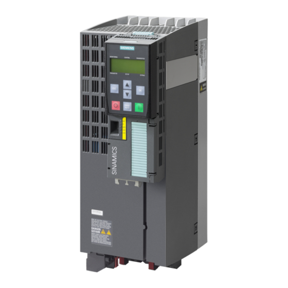
Siemens SINAMICS G120P Panduan Petunjuk Pengoperasian
Thermostatic switch
A thermostatic switch is installed to protect the braking resistor against overload. Its floating
contacts must be integrated in the fault chain on site.
Table 4- 2
Terminal
T1
T2
Max. connectable cross-section: 2.5 mm²
Integration of the thermostatic switch as release for switch-off via OFF2
The thermostatic switch must be connected to a free digital input so that the converter is
safely disconnected from the power supply if the braking resistor overheats. The digital input
of terminal strip X9/4 on the Power Module can be used for this purpose.
4.3

Parameterizing operation with braking resistor

For operation with a braking chopper, the braking power of the braking resistor must be
entered into parameter p0219. As a consequence, the Vdc max controller is automatically
deactivated (p1240 = 0) and the minimum ramp-down time (p1127) and the regenerative
power limit (p1531) are adapted.
Braking resistors
Operating Instructions, 10/2016, A5E32845373B AD
Thermostatic switch connection
Description of function
Thermostatic switch connection
4.3 Parameterizing operation with braking resistor
Technical data
Voltage: 250 V AC
Load current: max. 1 A
Electrical installation
17