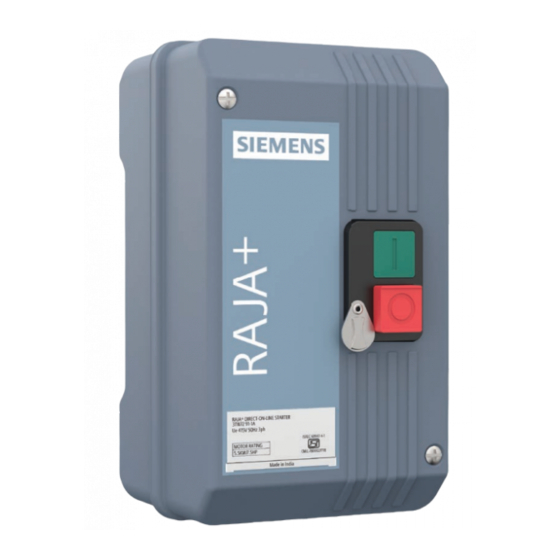
Siemens 3TW72 91-1 AW 69 Petunjuk Pemasangan, Pengoperasian & Pemeliharaan
Jelajahi secara online atau unduh pdf Petunjuk Pemasangan, Pengoperasian & Pemeliharaan untuk Pengontrol Siemens 3TW72 91-1 AW 69. Siemens 3TW72 91-1 AW 69 4 halaman. Dol starter

s
DOL Starter
3TW7291-1A
For dependable service, it is of utmost
importance that instructions given below are
followed for selection, inspection, installation,
commissioning, operation and maintenance.
Raja
DOL Starter (Self reset)
+
Selection of Starter
• Refer Table A for recommended selection of 3TW72 starters.
Table A: kW/HP Rating, Contactor MLFB's, thermal overload
relay range & fuse rating, Coil Voltage, Maximum full load
current for different types of motors.
• Recommended Submersible pump rating 5.5kW/7.5HP Max.
3
Fig. 1: DOL Starter
10
11
5
1
12
6
2
3
4
Fig. 2: Starter Inside View
Installation, Operation & Maintenance
Instructions
Please read and understand these instructions before
installating, operating, or maintaining the equipment. Keep for
future reference
Danger
Hazardous voltage can cause death or serious injury. Disconnect
power before working on equipment.
Warning
Automatic Motor Restart.
Can cause death, serious injury or property damage.
Do not use automatic reset mode when unexpected automatic
restart of the motor can cause injury to persons or damage to
equipment.
Reliable functioning of the equipment is only ensured with
certified components. Commissioning and maintenance by
qualified personnel only.
NOTICE
This product has been designed for environment A. Use of this product
in environment B may cause unwanted electromagnetic disturbances in
which case the user may require to take adequate mitigation measures.
IS/IEC 60947-4-1
1. 'ON' push buttons (green)
4
2. 'OFF' push button (red)
5
3. Cover fixing (Instrument Head) screws
4. Housing
1
5. Cover
2
6. Mechanical Latch (OFF push button) to be used for
6
preventing undesired ON operation of Starter
7. Name plate
7
9
7
8
1. Contactor
2. Overload Relay
3. Relay Dial
4. Red Knob
5. Contactor Incoming Terminal Screws
6. Contactor Outgoing Terminal Screws
7. Wiring diagram Label
8. Links
9. Gasket
10. Grommet
11. Mounting Screw hole
12. Contact Carrier
