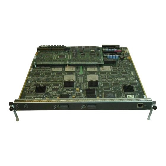
Cisco WS-X5161 Manual - Halaman 7
Jelajahi secara online atau unduh pdf Manual untuk Beralih Cisco WS-X5161. Cisco WS-X5161 33 halaman. Configuring token ring lan emulation
Juga untuk Cisco WS-X5161: Buletin Dukungan Produk (6 halaman)

Creating a LANE Plan and Worksheet
Connected to ATM-5.
Escape character is '^]'.
ATM>
After opening the session, you see the ATM> prompt. You then have direct access only to the ATM
module with which you have established a session.
Note
The ATM module uses a subset of Cisco IOS software. Generally, Cisco IOS software works the same on
the ATM module as it does on routers.
To configure the ATM module, you must use the ATM configuration mode in the Cisco IOS software. To
enter global configuration mode, enter the configure EXEC command at the privileged EXEC prompt
(ATM#). You see the following message, which asks you to specify the terminal, the NVRAM, or a file
stored on a network server as the source of configuration commands:
Configuring from terminal, memory, or network [terminal]?
If you specify terminal, the run-time configuration is used. You can then save the run-time configuration
into the NVRAM. If you specify memory, the run-time configuration is updated from the NVRAM. If you
specify network, the run-time configuration is updated from a file in a server on the network.
Note
You cannot configure from the network.
The ATM module accepts one configuration command per line. You can enter as many configuration
commands as you want.
You can add comments to a configuration file describing the commands you have entered. Precede a
comment with an exclamation point (!) or pound sign (#). Comments are not stored in NVRAM or in the
active copy of the configuration file. In other words, comments do not appear when you list the active
configuration with the write terminal EXEC command or list the configuration in NVRAM with the show
configuration EXEC command. Comments are stripped out of the configuration file when it is loaded to the
ATM module.
Creating a LANE Plan and Worksheet
Before you begin to configure Token Ring LANE, you must decide whether you want to set up one or
multiple ELANs. If you set up multiple ELANs, you must also decide where the servers and LECs will be
located, and whether to restrict the clients that can belong to each ELAN. Bridged ELANs are configured
just like any other LAN, in terms of commands and outputs. Once you have made those decisions, you can
configure Token Ring LANE.
Before implementing Token Ring LANE, it might help you to begin by drawing up a plan and a worksheet
for your own LANE scenario, showing the following information and leaving space to note the ATM
address of each LANE component on each subinterface for each participating switch:
•
•
•
•
Catalyst 5000 series switch interface where the LECS will be located.
Catalyst 5000 series switch interface and subinterface where the LES/BUS for each ELAN will be
located. For fault-tolerant operation, multiple servers can be on each ELAN.
Catalyst 5000 series switch ATM modules, subinterfaces, and VLANs where the LECs for each ELAN
will be located.
Name of the default ELAN (optional). The default Token Ring ELAN is the same as the default
TrCRF (1003). You can use the default Token Ring ELAN (trcrf-default) or configure a new one.
Token Ring LANE Configuration Task List
7
