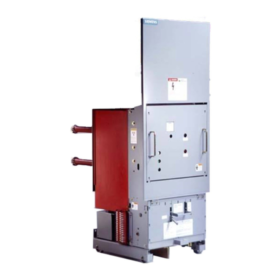
Siemens 15-FSV-750 Pengoperasian & Pemeliharaan Instalasi - Halaman 17
Jelajahi secara online atau unduh pdf Pengoperasian & Pemeliharaan Instalasi untuk Beralih Siemens 15-FSV-750. Siemens 15-FSV-750 48 halaman. Vacuum circuit breakers fsv series and msv series

Interrupter/Operator
Description
20
1 6
60
40
Typical Vacuum Tube and Operating Mechanism
Subassembly
Figure 5
15KV Vacuum Breaker
The close-open indicator (55), closing spring charge indicator
(58), and the operation counter (59) are fitted on the front of
the mechanism housing (60)"
The control connector (68"7) for the control and signalling ca
bles i s a 64 contact plug or 24 point terminal block appl ied
internally to the d rawout u nit
Breaker Pole (Fig u re 6)
The vacuum interrupter (30) is rigidly connected to the u pper
terminal ang le (27.1) and pole s u pport (20) by its terminal post
(31.2). The lower part of the interrupter is stabilized 2gainst
lateral forces by a centering ring (28.1) on the pole su pport
(40). The external forces d u e to switching operations and the
contact pressure are absorbed by the struts (28).
Current-Path Assembly (Figure 6)
The current-path assembly consists of the u pper terminal an
gle, 27.1. and pole s u p port. 20, th e stationary contact, 31, and
the moving contact, 36, which is con nected with the lower ter
minal, 29, by terminal clam p , 29 2, and a flexible shunt. 29.1.
Vacuum Interrupter (Fig ure 7)
The moving contacts' , (26), motion is aligned and stabi lized by
27
30
29
Mt
.ww
It
w�
(
-
59
55
58
Mechanism Housing
guide busing, (35) The metal bellows, (34), follows the travel
of contact, (36), and seals the interrupter against the surround
ing atmosphere.
The Arc-Quenching Principle
When the contacts separate, the cu rrent to be interrupted ini
tiates an ionized metal vapor arc discharge and flows through
this plasma until the next cu rrent zero. The arc is then extin
g u ished and the condu ctive metal vapor condenses on the
metal s u rfaces of the arcing chamber, (33), ( Fig . 7) within a
matter of microsecond s . As a result, the dielectric strength in
the increasing contact gap builds up very rapidly.
Below a limit of about 10,000 amperes, the arc is distributed
across the contacts and the arc is easily interru pted. At cur
rents larger than about 10,000 amperes the arcs own electro
magnetic forces cause the arc to contract to essentially a point
arc. If the contracted arc is allowed to remain stationary, it ov
erheats the contacts at the arc roots to the point where the
molten metal vapor does not al low the dielectric to rebuild d u r
ing the cu rrent zero and large magnitude currents could not
be interrupted .
Page 12
�
•
B
