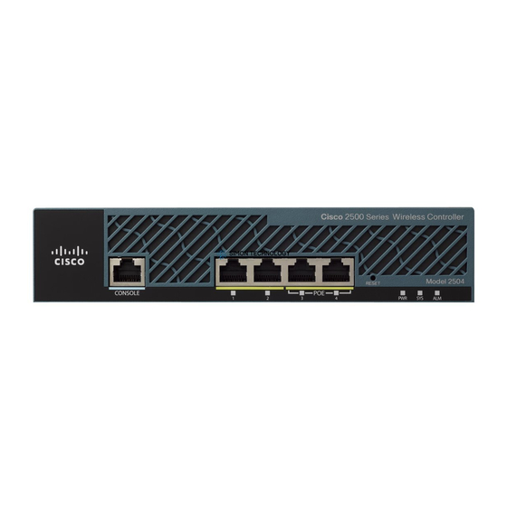
Cisco 2500 Series Panduan Instalasi - Halaman 3
Jelajahi secara online atau unduh pdf Panduan Instalasi untuk Router Jaringan Cisco 2500 Series. Cisco 2500 Series 12 halaman. Wireless controller
Juga untuk Cisco 2500 Series: Panduan Konfigurasi (19 halaman), Panduan Penyebaran (23 halaman), Panduan Konfigurasi (50 halaman), Panduan Memulai (47 halaman)

Warning
power switch, line voltages are present within the power supply even when the power switch is OFF
and the power cord is connected. For systems without a power switch, line voltages are present
within the power supply when the power cord is connected. (To see translated versions of this
warning, refer to the Regulatory Compliance and Safety Information document that accompanied the
router.)
Step 4
Step 5
Step 6
Step 7
Step 8
Figure 1
A
Removing AC and DC Power Supplies
This section describes how to remove an AC or DC power supply. Although an AC power supply is
shown in the illustrations that follow, the procedure is the same for removing both AC and DC power
supplies.
Take the following steps to remove a power supply:
Step 1
Do not touch the power supply when the power cord is connected. For systems with a
Turn the unit upside down so that the top of the chassis is resting on a flat surface, and the
front of the chassis is facing toward you. (See Figure 1, Part A.)
Remove the single screw located on the bottom of the chassis (on the side closest to you).
Note that the chassis is comprised of two sections: top and bottom.
If required, insert a medium-size flat-blade screwdriver into the slots shown in Figure 1,
Part A, and rotate the blade so that the top and bottom sections separate slightly.
Holding the chassis with both hands, position it as shown in Figure 1, Part B.
Pull the top section away from the bottom section. (See Figure 1, Part B.) The fit is very
snug, so it may be necessary to pry the chassis sections apart at one end and then the other
until they separate.
Chassis Cover Removal
Flat-blade screwdriver
Slot
Screw
B
Rear
Remove the screw located between the power switch and power connector.
(See Figure 2.) This screw secures the power supply to the chassis.
Installing Cisco AC and DC Power Supplies in Cisco 2500 Series Routers
Slot
Top section
Bottom section
Front
Left end
toward you
Removing AC and DC Power Supplies
3
