Actulux SVM 24V-5A Panduan Pengguna dan Instruksi Instalasi - Halaman 3
Jelajahi secara online atau unduh pdf Panduan Pengguna dan Instruksi Instalasi untuk Panel Kontrol Actulux SVM 24V-5A. Actulux SVM 24V-5A 11 halaman. For fire ventilation

- 1. Table of Contents
- 2. General Description
- 3. Safety Rules During Installation and Operation
- 4. Explosion Danger
- 5. Installation
- 6. Yearly Legal Requirement of Maintenance and Control
- 7. Connection to Motor- (Actuator) Outputs and Line Monitoring
- 8. Current Limiter Type LIP
- 9. Connection of Smoke-/Heat Detectors
- 10. Comfort Ventilation - Connection and Settings
- 11. Fuse Specifications
- 12. Connection of Weather Sensor / Close All Function
- 13. Special Functions
- 14. Cable Sizes
- 15. Part Nos. and Accessories
- 16. Technical Specifications
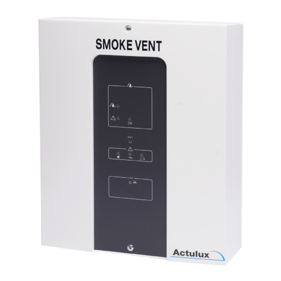
Control for Fire and Comfort Ventilation Type SVM 24V-5A / SVM 24V-8A
General description
The control panel can be used for electrical opening of e.g. skylights, smoke hatches or similar in
connection with fire- and comfort ventilation.
The control panel has different inputs with line monitoring which can be activated by e.g. fire switches,
smoke detectors, heat detectors, AFA systems and CCS systems.
For control of the indoor climate (comfort ventilation) manual switches, weekly timer, room thermostat
and outdoor weather sensors can be connected.
By means of LEDs in the the front panel the control indicates the operating condition (ok operation
and error- and alarm condition), just as it by means of the built-in potential free relay contacts can re-
lay operating information about ok operation and error- and alarm condition to other systems in the
building.
The polarity of the motor supply is reversed when opening or closing.
The control panel has built-in 72 hours battery back-up.
By a unique bus system consisting of a 3 wire cable the control panels can be mutually connected so
that up to 35 control panels can be connected and operate as an integrated system.
If the temperature in the control panel exceeds 75°C, the control panel will enter ALARM condition.
Connection of cables to the in- and outputs of the control panel is described in the connection drawing
on page 10-11.
A more detailled connection to the individual in- and outputs is described in the individual sections in
this manual. Selection of cable sizes on page 16-17.
By means of jumpers and dip switches the control panel has different setting possibilities for in- and
outputs. These settings are indicated in a complete table (please see section with jumper settings on
page 13).
Examples of types of openings systems and the max. power consumption which can be connected to
the control panel:
Type:
24V power supply:
SA Power Single
4A
SA Power Double
8A (2x4A)
SA Power Large
8A
SA Power Mini
2.5A
Rotary 100
2,5A
Others
See specification of max. power consumption on the opening
system
4
Control for Fire and Comfort Ventilation Type SVM 24V-5A / SVM 24V-8A
Safety rules during installation and operation
The control panel may only be installed and maintained by personnel authorized for installation of
automatic electrical fire ventilation equipment.
Explosion danger
The control panel is supplied with back-up batteries, which contain large amounts of energy which can
be released as explosion in case of wrong handling - the following safety rules must therefore always
be observed:
• Νever short-circuit a back-up battery.
• Do not use external chargers on installed batteries. If unauthorized chargers are used explosive
gasses can be released from the battery.
• Do not drop back-up batteries as strong acids can be released if they are broken.
Installation
The control panel can weigh up to 7 kg and must be installed on a stable wall. The mounting holes for
wall mounting are placed on the metal plate underneath the platic lid.
All cables are connected according to the drawing on the central pages and are dimensioned according
to table page 16. Keep in mind that the operating voltage from the control panel is 24V and that the
max. voltage drop is 15% which demands correct cable dimension according to table on page 17.
Please be aware that it often may be required (in order to keep the demands on the CE marking of the
complete installation or another law) that the control panel is supplied with 230V AC from separate
powerline with its own ground error circuit interruper, and that a repair interrupter is mounted on the
motor line.
After connection the control panel must charge the batteries min. 12 hours before complete testing.
Yearly requirement of maintenance and control (authorized)
The functions of the control panel and the opening system must be tested by authorized personnel
at least once a year. The control panel informs when the maintenance should be done. Then the
external LEDs on the front panel are running. The control panel and opening system are of course
still full operating. Please call a service technician at your earliest convenience in order to carry out
the maintenance and to test the control and opening system, in order to prepare it for another year
of operation. The legal requirements for this must be observed and the testing and control must as a
minimum include the following:
• Control that all opening systems move to full opening when the fire function is activated
- should not be carried out if the wind is more than 6 m/sec. as there might be a risk that the
opening system cannot close automatically.
• Control of the batteries. If the batteries are replaced it is important to use the same type as the
batteries are carefully chosen to be able to deliver the current, for which the control is specified.
• Control of in- and outputs on the control.
• Control of fire switches and smoke- and heat detectors.
The batteries should be replaced as required, however at least every third year!
Use the same brand.
5
