Sony CCU-790P Panduan Pengoperasian - Halaman 5
Jelajahi secara online atau unduh pdf Panduan Pengoperasian untuk Camcorder Sony CCU-790P. Sony CCU-790P 18 halaman. Camera control unit
Juga untuk Sony CCU-790P: Brosur & Spesifikasi (14 halaman)
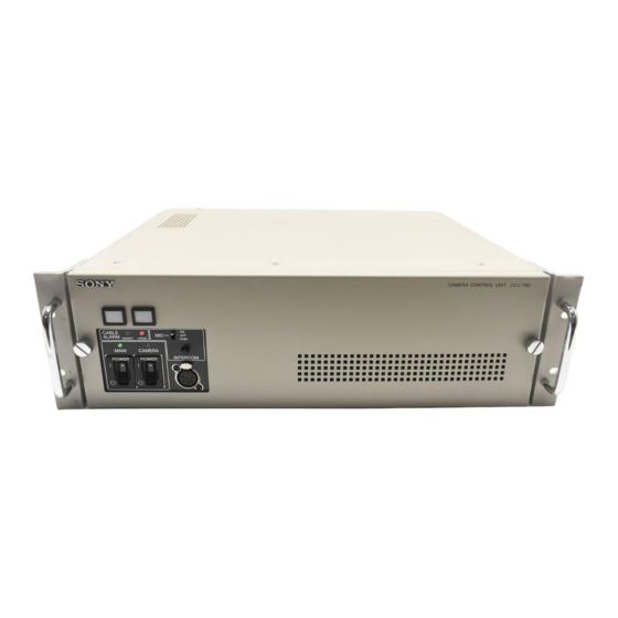
Function and Location of Parts and Controls
Front panel
h CABLE ALARM indicators
a Red tally lamp
Lights when the unit receives a red tally signal. When the
CALL button on the video camera, MSU-900/950 Master
Setup Unit, or RCP-750/751/920/921 Remote Control
Panel is pressed, the lamp lights if it is not lit, or goes dark
if it is lit. Attach a supplied number plate here.
For details on attaching a number plate, refer to the System
Manual.
b Green tally lamp
Lights when the unit receives a green tally signal. Attach
a supplied number plate here.
For details on attaching a number plate, refer to the System
Manual.
c MIC (microphone)/PGM (program audio) switch
ON: Turns on the headset microphone.
OFF: Turns off the headset microphone.
PGM: Outputs the program audio when the one ear
headset is used. When this position is selected, the
INTERCOM level control adjusts input level of the
program audio. The level of the PGM1 and PGM2 can
be adjusted by using the VR located on the panel side
of the internal AU board.
d INTERCOM level control
Adjusts the receiving level of the intercom.
a Red tally lamp
b Green tally lamp
c MIC/PGM switch
d INTERCOM level control
CABLE
ON
MIC
ALARM
OFF
SHORT
OPEN
PGM
MAIN
CAMERA
INTERCOM
POWER
POWER
e INTERCOM connector
f CAMERA POWER switch and indicator
g MAIN POWER switch and indicator
CAMERA CONTROL UNIT CCU-790
e INTERCOM connector (XLR 5-pin)
Connect a headset.
f CAMERA POWER switch and indicator
This switch controls the power supply to the video camera
when the MAIN POWER switch is set to the ON side (I
position). The indicator lights when power is supplied to
the video camera.
If an RCP-750/751/920/921 Remote Control Panel is
connected to this unit, the CAM PW switch on the panel
must be lit for control of the power supply to the camera
with this switch to be enabled.
g MAIN POWER switch and indicator
This switch turns on and off the power supply to the entire
camera system including this unit, a BVP-E10/E10P/
E10WS/E10WSP/E30/E30P/E30WS/E30WSP Color
Video Camera, and an RCP-750/751/920/921 Remote
Control Panel connected to the REMOTE connector. The
indicator lights when power is supplied to the system.
h CABLE ALARM indicators
OPEN: Lights when no triax cable is connected to the
CAMERA connector on the rear panel of the CCU-
790/790P, or when the load current is extremely low
even when a camera cable is connected.
SHORT: Lights when there is a current overflow in the
triax cable.
Function and Location of Parts and Controls
5