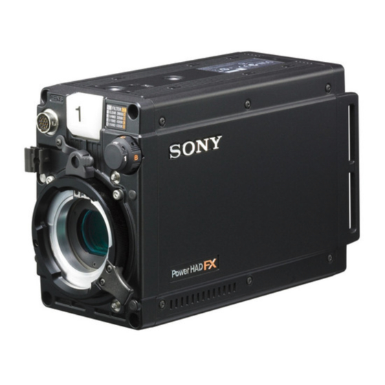
Sony Power HADFX HDC-P1 Panduan Pengoperasian - Halaman 16
Jelajahi secara online atau unduh pdf Panduan Pengoperasian untuk Kamera Digital Sony Power HADFX HDC-P1. Sony Power HADFX HDC-P1 36 halaman. Hd multi purpose camera
Juga untuk Sony Power HADFX HDC-P1: Brosur (36 halaman), Brosur (4 halaman), Brosur (4 halaman), Brosur (2 halaman)

3
Rotate the menu control knob to align the pointer to
the item to be set and push on the knob.
To use the level indicator
Setting INDICATOR to ON displays the level indicator on
the monitor. You can set the display format with the menu
items below.
MODE: Set the type and position of the indicator.
LEVEL: Set the density and the response speed of the
indicator.
GAIN: Set the sensitivity of the indicator.
OFFSET: Set the offset of the focus detection value.
1) Normally, the sensitivity of the indicator is automatically set to
the optimum value in conjunction with the AREA MARKER
SIZE set value. Use this setting when an optimum sensitivity
value cannot be obtained, depending on the shooting
environment.
2) Normally, the optimum offset is automatically set in conjunction
with the AREA MARKER SIZE and MASTER GAIN set values.
Use this setting when the optimum offset cannot be obtained,
depending on the shooting environment.
To use the area marker
Setting AREA MARKER to ON displays the detection area
of the focus as a marker on the monitor.
You can set the size and position of the detection area with
the menu items below.
SIZE: The size of the detection area can be changed. (If
the area size is too large, both the subject and the
background are included in the area, making the
indicator display easily deviate from the subject.)
POSITION: Roughly set the position of the detection area.
POSITION H: Finely adjust the position of the detection
area in the horizontal directions.
POSITION V: Finely adjust the position of the detection
area in the vertical directions.
4
Rotate the menu control knob to display the desired
setting and push on the knob.
5
To finish the adjustments, set the DISPLAY/MENU
switch to OFF to exit Menu mode.
Notes
• The INDICATOR and effect area marker cannot be
displayed at the same time. The one that was set to ON last
takes priority.
• The AREA MARKER and aspect safety marker cannot be
displayed at the same time. The one that was set to ON last
takes priority.
• When displaying the focus assist indicators, check that the
flange focal length has been precisely adjusted.
See "Adjusting the Flange Focal Length" (page 14) for the
flange focal length.
16
Menus
Menus
The menus displayed on the monitor connected to the VBS
connector or SDI 2 connector enable various settings of the
camera to be configured.
The following controls are used to operate the menus.
1)
Turn the menu control knob on the rear panel to select menu
2)
items or values, and push on it to register (enter) the selection.
Rear
Displaying Menu Pages
To display a menu page
Set the DISPLAY/MENU switch to MENU.
The menu page last accessed will be displayed. If it is the first
time, the CONTENTS page of the USER menu will be
displayed.
To display the TOP MENU screen
If you set the DISPLAY/MENU switch to MENU while holding
the menu control knob pressed, "TOP" is displayed at the
upper right corner of the screen.
Turn the menu control knob to move the pointer on the display
to "TOP" and push on the knob. The TOP MENU screen is
displayed, listing the available menus.
Menu
USER
USER MENU
CUSTOMIZE
DISPLAY/MENU switch
Menu control knob
Rotate
Push on
<TOP MENU>
USER
USER MENU CUSTOMIZE
ALL
OPERATION
PAINT
MAINTENANCE
FILE
DIAGNOSIS
Purpose
This menu can include menu pages selected
from among the OPERATION, PAINT,
MAINTENANCE, FILE, and DIAGNOSIS menus,
for convenience (see the table on page 18 for the
default configuration). Changing, adding, and
deleting pages can be performed with the USER
MENU CUSTOMIZE menu.
This menu allows you to edit the USER menu.
For details, see "Editing the USER Menu" (page
18).
