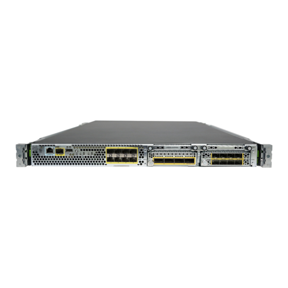
Cisco Firepower 4110 Manual - Halaman 19
Jelajahi secara online atau unduh pdf Manual untuk Perangkat Keras Jaringan Cisco Firepower 4110. Cisco Firepower 4110 26 halaman. Rack-mount and ground the chassis
Juga untuk Cisco Firepower 4110: Panduan Pemeliharaan dan Peningkatan (20 halaman), Manual (36 halaman), Manual (8 halaman), Manual (42 halaman), Memulai (42 halaman)

Installation, Maintenance, and Upgrade
Step 10
Set the DC disconnect switch in the circuit to ON. In a system with multiple power supplies, connect each power supply
to a separate DC power source. In the event of a power source failure, if the second source is still available, it can
maintain system operation.
Step 11
Verify power supply operation by checking the power supply LED on the front of the chassis. See
for a description of the LEDs.
Secure the Power Cord on the AC Power Supply Module
Tie Wrap and Clamp
Safety Warnings
Warning
Warning
Warning
To secure the power supply module against accidental removal and thus prevent disrupting system
performance, use the tie wrap and clamp provided in the accessories kit that ships with your Firepower
4100. There are two different tie wrap and clamp combinations to be used with either the Flextronics or
Artesyn power supply module.
To verify which power supply module you have, look at the vendor name on the top of the power supply
module. If you cannot remove the power supply module, you can count the number of full hexagonal
vent holes on the front of the power supply module in the row directly next to the word 'FAIL.' Flextronics
has five holes and Artesyn has four holes.
The black tie wrap is used with the Flextronics power supply module and the off-white tie wrap is used
with the Artesyn power supply module. The black clamp works with both. See the figures below.
Take note of the following component replacement safety warnings:
Statement 1028 More Than One Power Supply
This unit might have more than one power supply connection. To reduce risk of electric shock, remove
all connections to de-energize the unit.
Statement 1030 Equipment Installation
Only trained and qualified personnel should be allowed to install, replace, or service this equipment.
Statement 1073 No User-Serviceable Parts
There are no serviceable parts inside. To avoid risk of electric shock, do not open.
Secure the Power Cord on the AC Power Supply Module
Installation, Maintenance, and Upgrade
Front Panel LEDs
19
