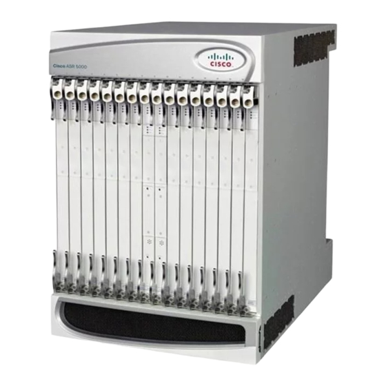
Cisco ASR 5000 Panduan Instalasi - Halaman 17
Jelajahi secara online atau unduh pdf Panduan Instalasi untuk Gerbang Cisco ASR 5000. Cisco ASR 5000 37 halaman. Applying power and verifying the installation
Juga untuk Cisco ASR 5000: Panduan Instalasi (18 halaman), Panduan Instalasi (33 halaman), Prosedur Instalasi (8 halaman)

Applying Power and Verifying the Installation
Table 11: SPIO Run/Fail LED States
Color
Green
Red
None
SPIO Active LED States
The Active LED on the SPIO indicates that the software is loaded on the card and that the card is ready for
operation. For the SPIO installed in chassis slot 24, this LED is steady green during normal operation. For
the SPIO installed in slot 25, this LED is off during normal operation.
If the LED is not green, use the troubleshooting information in the table to diagnose the problem.
Table 12: SPIO Active LED States
Color
Green
Description
Troubleshooting
Card powered with no
None needed.
errors detected
Card powered with
Errors were detected during the POSTs. It is likely that the errors
error(s) detected
were logged to the system's command line interface during the
boot process.
Refer to the System Administration Guide for troubleshooting
information.
Card is not receiving
Verify that the POWER LEDs on the PFUs are green. If they are
power
not, refer to
troubleshooting information.
Verify that the power source is supplying ample voltage and
current to the chassis.
Verify that the card is properly installed per the instructions in
this document.
If all of the above suggestions have been verified, it is possible
that the SPIO is not functional. Please contact your service
representative.
Description
Troubleshooting
Card is active
None needed for SPIO in slot 24. If green for SPIO in slot 25,
verify that SPIO in slot 24 is installed according to the instructions
in this document.
Checking the LEDs on the SPIO(s)
Checking the LED on the PFU, on page 5
ASR 5000 Installation Guide
for
17
