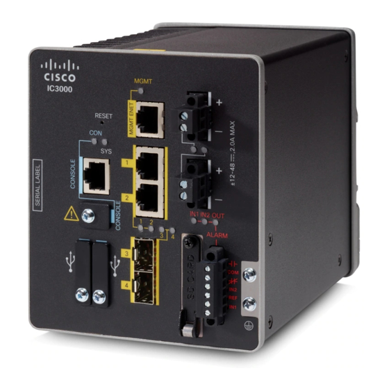
Cisco IC3000 Panduan Pemasangan Perangkat Keras - Halaman 30
Jelajahi secara online atau unduh pdf Panduan Pemasangan Perangkat Keras untuk Gerbang Cisco IC3000. Cisco IC3000 37 halaman. Industrial compute gateway
Juga untuk Cisco IC3000: Dokumentasi Produk (12 halaman)

Attaching the DC Power Connectors to the Device
Figure 12: Torquing the Power Connector Captive Screws
WARNING: An exposed wire lead from a DC-input power source can conduct harmful levels of electricity. Be sure that
no exposed portion of the DC-input power source wire extends from the power and relay connector. Statement 122
Step 8
Connect the other end of the positive wire to the positive terminal on the DC power source, and connect the other end of
the return wire to the return terminal on the DC power source.
When you are testing the device, one power connection is sufficient. If you are installing the device and are using a second
power source, repeat steps 4 through 8 using the second power connector.
Attaching the DC Power Connectors to the Device
To attach the power connectors to the front panel of the device, follow these steps:
1. Insert one power connector into the DC-A receptacle on the device front panel, and the other into the
DC-B receptacle.
2. Use a ratcheting torque flathead screwdriver to tighten the captive screws on the sides of the power
connectors to 2 in-lb (0.23 N-m).
3. When you are testing the device, one power source is sufficient. If you are installing the device and are
using a second power source, repeat this procedure for the second power connector (DC-B), which installs
just below the primary power connector (DC-A).
Cisco IC3000 Industrial Compute Gateway Hardware Installation Guide
28
Connecting the Cisco IC3000
