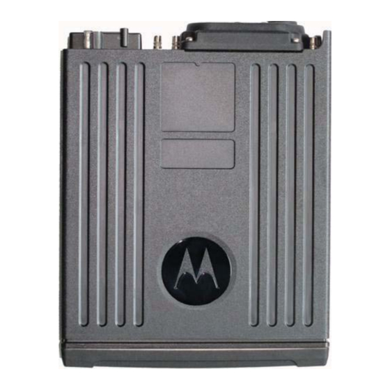
Motorola APX8500 Panduan Instalasi - Halaman 7
Jelajahi secara online atau unduh pdf Panduan Instalasi untuk Radio Dua Arah Motorola APX8500. Motorola APX8500 25 halaman. Two-way radios

Table of Contents
4.4
Accessory Connector Assembly Details (P2) ................................................................................ 4-9
4.4.1
Disassembly and Assembly .............................................................................................. 4-9
4.4.1.1
4.4.1.2
4.5
Motorola Branded SB9600 Siren Connection to APX 8500......................................................... 4-11
4.6
Compatibility of Emergency when Attaching a Motorola Branded SB9600 Siren........................ 4-13
Chapter 5
Motorcycle Radio Installation ............................................ 5-1
5.1
Motorcycle Radio Description ........................................................................................................ 5-1
5.1.1
Transceiver Enclosure ...................................................................................................... 5-1
5.1.2
Control/Display Unit .......................................................................................................... 5-1
5.1.3
Control Head Cable .......................................................................................................... 5-1
5.1.4
Microphone ....................................................................................................................... 5-2
5.1.5
External Speaker .............................................................................................................. 5-2
5.1.6
Headset Capability............................................................................................................ 5-2
5.1.7
Antenna ............................................................................................................................ 5-2
5.1.8
Ignition Sense (ACC) Wire................................................................................................ 5-2
5.2
Installation Overview...................................................................................................................... 5-3
5.2.1
General ............................................................................................................................. 5-3
5.2.2
Important Motorcycle Installation Hints ............................................................................. 5-4
5.2.3
Parts Identification ............................................................................................................ 5-5
5.2.4
Order of Installation .......................................................................................................... 5-5
5.3
Installing the Universal Mounting Plate.......................................................................................... 5-6
5.4
Installing the Speaker and Control Head ....................................................................................... 5-7
5.4.1
Handlebar Installation with Speaker and Control Head Mounted Together...................... 5-8
5.4.2
Fuel Tank Console Installation with Speaker and Control Head Mounted Together ........ 5-9
5.4.3
Handlebar Installation with Speaker and Control Head Mounted Separately ................. 5-11
5.4.4
Fuel Tank Console Installation with Speaker and Control Head Mounted Separately ... 5-12
5.5
Installing the Speaker .................................................................................................................. 5-14
5.6
Installing the Microphone Hang-Up Clip ...................................................................................... 5-14
5.6.1
Extension Bracket Mounting ........................................................................................... 5-14
5.6.2
Speaker/Control Head Bracket Side Mounting ............................................................... 5-14
5.6.3
Other Hang-Up Clip Mounting ........................................................................................ 5-15
5.7
Installing Antenna Base, Cables and Multiplexer ........................................................................ 5-15
5.8
Installing the Antenna .................................................................................................................. 5-21
5.9
Cable Routing .............................................................................................................................. 5-21
5.10 Installing the Weather-Resistant Enclosure................................................................................. 5-23
5.11 Transceiver, Cabling and Multiplexer Installation ....................................................................... 5-24
5.11.1 Installing Cabling in the Enclosure.................................................................................. 5-24
5.11.2 Installing the Transceiver ................................................................................................ 5-25
5.12 Installing the Emergency Switch Option ...................................................................................... 5-27
5.13 Installing the External Alarm Relay Option .................................................................................. 5-27
5.14 Installing the Headset Accessory................................................................................................. 5-27
5.15 Installing the O5 Control Head Sunshield.................................................................................... 5-29
5.16 Horn/Lights Wiring ....................................................................................................................... 5-31
5.17 Emergency Switch Wiring............................................................................................................ 5-31
Chapter 6
Finishing the Installation.................................................... 6-1
6.1
Cable Connection .......................................................................................................................... 6-1
6.1.1
O2 Control Head ............................................................................................................... 6-1
6.1.2
O3 Control Head ............................................................................................................... 6-1
MN003109A01
Disassembly ............................................................................................................ 4-9
Assembly ............................................................................................................... 4-10
Wire
Wire
............
.............
.....................
....................
rcycle
rcycle Inst
allation H
cation ............................
cation ....................
lation ................
lation ...............................
ounting Plate....................
ounting Plate..........
Control Head .....................
Head ........
with Speaker and Control
th Speaker and C
lation with Speaker and Co
ation with Speaker
Speaker and Control Head
tion
eaker and Control Head
with Speaker and Control
with Speake
and Contr
.........................................
....................................
...............................
.......
.......................
.........................
........................
nting .........
g ....
.....
......
v
