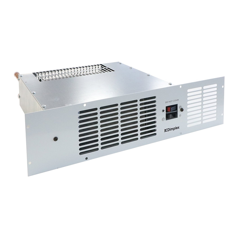
Dimplex BUH19BWS Petunjuk Instalasi dan Pengoperasian - Halaman 3
Jelajahi secara online atau unduh pdf Petunjuk Instalasi dan Pengoperasian untuk Pemanas Listrik Dimplex BUH19BWS. Dimplex BUH19BWS 4 halaman. Hydronic base unit heater
Juga untuk Dimplex BUH19BWS: Petunjuk Pengoperasian (4 halaman)

Power supply connection
WARNING: THIS APPLIANCE MUST BE EARTHED
This heater must be used on an AC~ supply only and the
voltage marked on the heater must correspond with the
supply voltage.
The installation of this appliance should be carried out by
a an electrician or competent person in strict accordance
with the current IEE Wiring Regulations and relevat Building
Regulations.
Before undertaking installation work, ensure the electricity
supply is disconnected from any relevant wiring.
The appliance is fitted with 2 meters of flexible cable 3 x
0.75mm² for electrical connection. The cable may be used to
connect the heater to the fixed wiring of the premises through
a suitable connection box. The supply circuit to the heater
must incorporate a double pole isolating switch having a
contact separation of at least 3mm. The power supply cable
should be routed through the plinth space to the connection
box, ensuring that the cable is left with enough slack to allow
removal of the appliance for maintenance. The cable must
be protected from any sharp edges.
Fitting the rear support bracket
The heater is supplied with a rear support bracket. Fit to the
back of the appliance with the two black screws supplied.
Adjust the rear support bracket so that the product is level.
The slots in the rear of the support bracket allow it to be
adjusted to the required height.
Marking the fixing positions
Slide the heater in to position in the plinth aperture with the
front edge just behind the line of the plinth.
Note: Ensure that flexible pipes are not kinked and that the
electrical cord is not in contact with hot surfaces.
Replace the plinth and bring the appliance forward so that
the front edge slightly projects through the plinth.
Position the grille in front of the heater and fix with two screws
(smaller screws).
Mark the eight fixing holes (two on each side, two on the
top and two on the bottom). Remove the grille and drill 2mm
pilot holes.
Mounting the heater in to the plinth
Make sure the heater is adequately supported and that the
air inlet slots are not obstructed. Fix the grille to the heater
and use the eight longer screws provided to secure the heater
to the plinth.
Operation
1. Switch on the electricity supply to the heater
2. Winter use for heating:
Set the Winter/Summer switch to (Winter position)
Select either low or boost fan speed on the changeover
switch depending on heat required.
3. Turn ON the central heating system.
4. As hot water reaches the heat exchanger the low limit.
Thermostat should cut in and the fan will start to operate
(set at 38ºC).
5. Summer use – cool blow.
The hydronic base unit heater may be used in Summer
to provide air circulation without heat.
Set the winter / Summer switch to
and Choose between low
In this position the fan will run at the selected speed until
manually reset.
Wiring Diagram
Winter/Summer switch
Boost/Low speed switch
(Summer position),
or boost fan
speed.
Fig. 4
