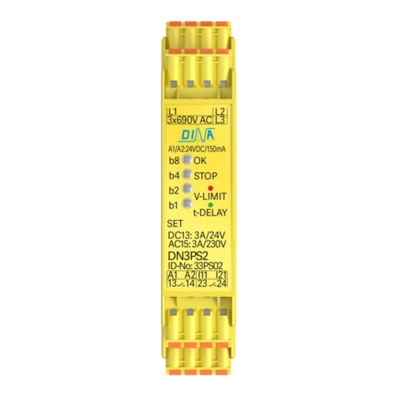
DINA DN3PS2 Buku Petunjuk Asli - Halaman 11
Jelajahi secara online atau unduh pdf Buku Petunjuk Asli untuk Beralih DINA DN3PS2. DINA DN3PS2 16 halaman. Standstill monitoring for one and three phases motors without sensor system
Juga untuk DINA DN3PS2: Buku Petunjuk Asli (12 halaman)

DN3PS2
Überwachung einer Schutzeinrichtung
Überwachung einer Schutzeinrichtung
Betriebsart FA1
• Für die Überwachung einer Schutzeinrichtung
sind die Eingänge I11 und I21 spannungslos.
• Die Stillstandsüberwachung ist dadurch ständig aktive.
• Über die Kontakte 13-14/ 23-24 (serielle Schaltung) wird
die Verriegelung der Schutzeinrichtung angesteuert.
• Die Kontakte schließen erst dann, wenn der Antrieb
der Anlage im Stillstand harrt.
• Danach ist die Schutzeinrichtung entriegelt.
(2) Verriegelung der Schutzeirichtung
Stillstandsüberwachung
Betriebsart FA2
• Für die Überwachung des Stillstands werden die
Eingänge I11 und I21 über den Schalter der
Schutzeinrichtung mit 24V DC angesteuert.
• Im Automatikbetrieb (Schutzeinrichtung geschlossen)
ist die Überwachung nicht aktive.
• 13-14 und 23-24 sind dauerhaft geschlossen und die
LED STOP leuchtet grün.
• Ein Öffnen der Schutzhaube bewirkt den Wechsel zu
Betriebsart FA1.
Eine Antriebsbewegung löst die Not-Halt Funktion aus.
•
(1) Schutzeinrichtung Schalter
L1
L2
L3
14
24
V 1
U1
W1
M
3
U2
V1
U1
V2
W1
W2
DN3PS2
L1
L2
L3
V 1
U1
M
3
U2
V1
U1
W1
W2
24V DC
Test?
A1
13
23
b8
SET
L1
b4
L2
DN3PS2
b2
L3
b1
A2
I11
121
14
24
14
(1)
24V DC
Stand: 18.04.2018
Safety cover monitoring
• The inputs I11 and I21 are dead for the monitoring of
the safe cover.
• The standstill monitoring is thereby always active.
• The safe cover enabling is controlled by the contact
13-14/ 23-24 (serial circuit).
• The contacts close after the permanent standstill of
the drive of the construction.
• The safety cover is unlocked.
(2) safety cover interlocking
24V DC
Test?
A1
13
23
b8
SET
L1
b4
L2
DN3PS2
b2
L3
W1
b1
A2
I11
121
14
24
V2
(2)
Standstill monitoring
• The inputs I11 and I21 are controlled by the safety cover
switch with 24V DC during the standstill monitoring.
• During the automatically function mode the
monitoring is inactive (safety cover is closed).
• 13-14 and 23-24 are permanently closed and the
LED STOP illuminates green.
• An opening of the safety cover activates the function
mode FA1.
A drive movement causes an emergency stop.
•
(1) safety cover switch
L1
L2
L3
23
U1
3
U2
24
U1
W2
Seite 11 von 16
Function mode FA1
Function mode FA2
24V DC
Test?
A1
b8
SET
L1
b4
L2
DN3PS2
b2
V 1
L3
W1
b1
M
A2
I11
121
V1
V2
(1)
W1
24V DC
Date: 2018-04-18
23
13
23
14
24
Page 11 of 16
