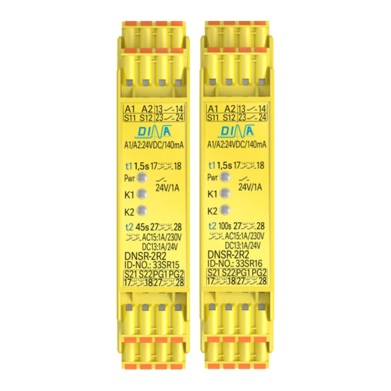
DINA Elektronik 33SR15 Buku Petunjuk Asli - Halaman 11
Jelajahi secara online atau unduh pdf Buku Petunjuk Asli untuk Alat Ukur DINA Elektronik 33SR15. DINA Elektronik 33SR15 16 halaman.

DNSR-2R2
Original Betriebsanleitung
Anschlussklemmen 33SR15 bis 33SR18
A1:
S11:
S12:
S21:
S22:
PG1/ PG2:
13
17
23
PG2
27
Produktbeschreibung 33SR15 bis 33SR18
• DNSR-2R2 verfügt über rückfallverzögerte Kontakte
zur Freigabe von Steuerstromkreisen.
• Der Anschlussplan ist am Gerät seitlich.
• Die steckbaren Klemmen sind Vertausch sicher.
• Durch verbinden der Klemme PG1 zu 24V DC schließt
der Kontakt 13
14 und öffnet sofort nach der
Trennung.
• 17
18 schließt bei Verbinden S11 mit S12.
• 17
18 öffnet rückfallverzögert (t1) beim
Unterbrechen S11 von S12. LED K1 blinkt während (t1).
• Die Funktion ist retriggerbar bei ID-No.: 33SR15, 33SR16
und 33SR18.
• Der Kontakt 23
Klemme PG2 mit 24V DC und öffnet bei Trennung.
• 27
28 schließt bei Verbinden S21 mit S22.
• 27
28 öffnet rückfallverzögert (t2) beim
Unterbrechen S21 von S22. LED K2 blink während (t2)
Verwendung 33SR15 bis 33SR18
DNSR-2R2 ist geeignet zum Einsatz beispielsweise zur:
• Energietrennung von den Antrieben über sichere rück-
fallverzögerten Kontakt 17
• DNSR-2R2 kann in Sicherheitskreisen nach VDE 0113
Teil 1 eingesetzt werden mit maximal Kategorie 3/ PLd
nach DIN EN ISO 13849-1.
• DNSR-2R2 ist in 22.5mm Kunststoffgehäuse zur
Montage im Schaltschrak auf einer 35mm Hutschiene.
• Ein Anschlussplan ist an der Geräteseite.
Stand 30.08.2017
24V DC, A2: 0V
Steuereingang (15V DC±0,5V)
für 17
18
Steuerspannung (15V DC)
Steuereingang (12V DC±0,5V)
für 27
28
Steuerspannung (12V DC)
Steuereingänge über 24V DC
für 13
14 und 23
14: Startkontakt steuerbar über PG1.
Andere Funktionen sind möglich.
18: Sicherer Kontakt,
rückfallverzögert (t1)
24: Startkontakt steuerbar über
Andere Funktionen sind möglich
28: Sicherer Kontakt
rückfallverzögert (t2)
24 schließt beim Verbinden der
18 und 27
Seite 11 von 16
Original Instruction Manual
Connection terminals 33SR15 to 33SR18
A1:
S11:
S12:
S21:
S22:
PG1/ PG2:
24
13
17
23
27
Product description 33SR15 to 33SR18
• DNSR-2R2 has OFF-delayed contacts to enable
control circuits.
• The connection schematic is at the side of the unit.
• The pluggable terminals are coded against
interchange.
• 13
14 closes by connecting the terminal PG1 to
24V DC and opens after disconnecting.
• 17
18 closes by connecting S11 to S12.
• 17
18 opens OFF-delayed by disconnecting S11
of S12. LED K1 is flashing during (t1).
• The function is retrigger able at ID-No.: 33SR15,
33SR16 and 33SR18.
• 23
24 closes by connecting the terminal PG2 to
24V DC and opens after disconnecting.
• 27
28 closes by connecting S21 to S22.
• 17
18 opens OFF-delayed by disconnecting S21
of S22. LED K2 is flashing during (t2).
Usage 33SR15 to 33SR18
DNSR-2R2 is adapted to be used as example to:
• Turn off the power of the drives with safe contact
28.
17
18 and 27
• DNSR-2R2 can be used in safety circuits according to
VDE 0113 part 1 with maximal category 3 / PLd
according to DIN EN ISO 13849-1.
• DNSR-2R2 is mounted in a 22.5mm synthetically
housing to be installed on a 35mm DIN rail.
• A connection plan is on the side of the unit.
Date 2017-08-30
24V DC, A2: 0V
Control input (15V DC±0,5V)
for 17
18
Control voltage (15V DC)
Control input (12V DC±0,5V)
for 27
28
Control voltage (12V DC)
Control inputs via 24V DC
for 13
14 and 23
14:
Start contact controlled via PG1
Other functions are possible.
18: Safe contact
OFF-delayed (t1)
24: Start contact controlled via PG2
Other functions are possible.
28: Safe contact OFF-delayed (t2)
28.
Page 11 of 16
24
