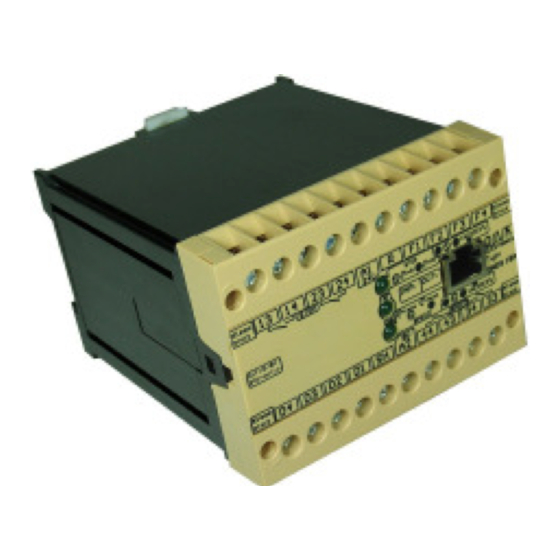
DINA Elektronik DNDS 2GA Buku Petunjuk Asli - Halaman 9
Jelajahi secara online atau unduh pdf Buku Petunjuk Asli untuk Unit distribusi daya DINA Elektronik DNDS 2GA. DINA Elektronik DNDS 2GA 20 halaman.

Instruction manual DNDS Kompakt
Function description: DNDS 1C, 1D, 1FA & 1GA
DNDS 1C, 1D, 1FA & 1GA:
The DNDS acts as a failsafe monitor of a rotary respectively linear motion and standstill. The speed monitor shut-
down trigger point can be programmed via 4 inputs (D1–D4). This shutdown trigger point can be further modified
from 100% down to 5 % via the 4inputs (F1–F4)
DNDS 1C, 1D has an internal (R) input to switch between constant and variable creep velocity (see table 1 and 2).
The motion detection can be monitored via 2 PNP-proximity sensors or a rotary encoder.
If PNP-proximity sensors are used, attention must be paid to mount them in a way, so always one of the two sen-
sors is activated.
Rotary encoders can only be connected using a DNIA adaptor (for the rotary encoder specifications, see the DNIA
operating instructions).
DNDS 1FA, 1GA has an external (R) input to switch between constant and variable creep velocity. A further exter-
nal (SH) input is used for switching over between creep velocity and standstill (see table 1 and 2).
For motion monitoring a rotary encoder is required. The Rotary encoder is connected via a DNDA 15/8 or DNDA
25/8 adaptor to the DNDS 1FA, 1GA
Function of the inputs of DNDS 1C, 1D, 1FA & 1GA
D-inputs:
Setting the automatic operation mode speed in 16 steps (00-15 = 100 – 800 Hz, table 1)
-
D-inputs are only of importance if at least one F-input is connected to 24V
-
If the F-inputs are not active (open) and the R-input is active, the active D-inputs determine the value of the tool
-
setting speed.
F-inputs:
F-inputs reduce the stting value via the D-inputs in 15 steps, 01-15 = 25-100%.
-
The F-inputs are also a switch over between tool setting (all F= open) and automatic operation mode (any F con-
-
nected with 24V). The tool setting speed is variable between 1-20 Hz or constant 5 Hz.
The F-inputs setting is store internally to determine the tool setting speed, if all F inputs are switched off. The
-
stored F setting is valid until the equipment is powered off.
The value of the tool setting speed is determined by the stored F-inputs, if the D-inputs are open and the R-input
-
is active.
R-input:
R-input works only if the F-inputs are switched off (open).
-
If the R- and D-inputs are active the creep rate is determined by the active D-inputs. (see Table 1)
-
If the D-inputs are open the tool setting speed is determined by the stored F setting .
-
If the R-input and the Finputs are not active, the standstill is monitored.
-
R- and SH inputs must not be connected to 24V at the same time.
-
SH-input: DNDS 1FA, 1GA only
The SH input is used to switch between tool setting speed and standstill (50Hz and 5Hz)
-
The SH-input works only if the R-input and all F-inputs are switched off (open).
-
If the SH-input and the F-inputs are open the standstill will be monitored.
-
If the SH-input is active (SH connected to 24V) and the F-inputs are open the tool setting speed will be moni-
-
tored.
Products: safety
technique
DNDS KOMPAKT
Version 04 / 2011.03.16
page 9 from 20
