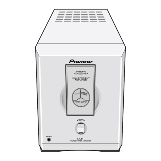
Pioneer M-LA21 Panduan Servis - Halaman 12
Jelajahi secara online atau unduh pdf Panduan Servis untuk Penguat Pioneer M-LA21. Pioneer M-LA21 24 halaman.
Juga untuk Pioneer M-LA21: Panduan Servis (24 halaman)

1
M-LA21
4. PCB CONNECTION DIAGRAM
4.1 AMP ASSY
A
NOTE FOR PCB DIAGRAMS :
• Part numbers in PCB diagrams match those in the schematic
diagrams.
• The parts mounted on this PCB include all necessary parts for
several destinations.
For further information for respective destinations, be sure to
check with the schematic diagram.
• View point of PCB diagrams.
Connector
B
P.C.Board
C
D
A
12
1
2
Capacitor
SIDE A
SIDE B
Chip Part
2
3
A
AMP ASSY
WH601
B
WH1
B
CN603
CN1
16VAC1
GND
16VAC2
MUTE
CTLGND
PWRCTL
W605
EC633
SIDE A
3
4
R670
EC625
Z2
W601
EC620
W603
P3
EC624
BLK
BRN
RED
ORN
YEL
WHT
EC622
P2
W606
IC604
EC621
EC626
Q617
4
Z1
W602
