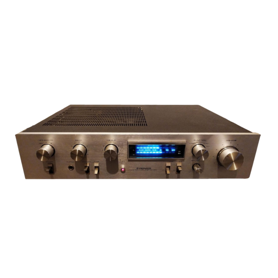
Pioneer SA-610 Panduan Servis - Halaman 10
Jelajahi secara online atau unduh pdf Panduan Servis untuk Penguat Pioneer SA-610. Pioneer SA-610 24 halaman.

8 . A D J U S T M E N T S
8 . 1 I D L E C U R R E N T A D J U S T M E N T
1. Set the SPEAKERS selector to the A position,
and connect an 8Q resistor to the speaker out-
put terminals.
2. Turn the VOLUME control down to minimum
level, turn the power on, and wait about 10
minutes.
3. Connect a DC voltmeter to the TP terminals
(Lch; TP4 and TP3, Rch; TP2 and TP1) of the
AF Amplifier Assembly (GWK-144).
4. Check that the voltage between TP4 and TP3
(Lch) lies within the DC 4mV-50mV range
then make a similar check for the Rch (between
TP2 and TP1). If the voltage is less than 4mV,
cut jumper wire A (Lch), and jumper wire B
(Rch). If the voltage exceeds 70mV, check for
circuit failure.
8.2 OUTPUT INDICATOR ADJUSTMENT
1. Set the TONE CONTROL to the center position.
2. Set the SPEAKERS selector to the A position,
and connect an 8O resistor and AC voltmeter to
the speaker output terminals.
3. Set the FUNCTION switch to the AUX position,
and apply a 7kHz, 150mV signal to the AUX
terminals.
4. Adjust the VOLUME control so that the voltage
on the output terminals (SPEAKERS) read 9V
( A C ) .
5. Adjust VR1 (Lch) and VR2 (Rch) of the in-
dicator assembly so that the output power
indicator read 10 watts.
AF Amplifier Assembly
( G W K - 1 4 4 )
@ Jumper wire A
J u m p e r
--l
@vR2
vR1
F.L Meter Assembly e
F i g . 8 - 1 A d j u s t m e n t p o i n t
1 0
