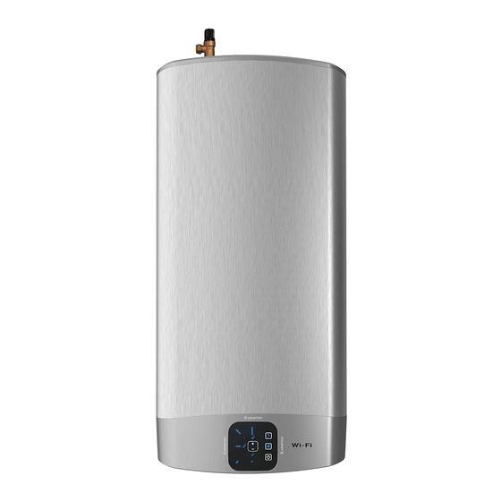
Ariston VLS EVO 45 WiFi Manual Petunjuk Perakitan dan Pengoperasian - Halaman 11
Jelajahi secara online atau unduh pdf Manual Petunjuk Perakitan dan Pengoperasian untuk Pemanas Air Ariston VLS EVO 45 WiFi. Ariston VLS EVO 45 WiFi 25 halaman. Unvented water heater

WORKED EXAMPLE
The example below is for a G 1/2" temperature & pressure relief valve with a discharge pipe (D2) having
4 no. elbows and length of 7 m from the tundish to the point of discharge.
From Table 2
Maximum resistance allowed for a straight length of 22 mm copper discharge pipe (D2) from G 1/2" T
& P valve is 9 m. Subtract the resistance for 4 no. 22 mm elbows at 0.8 m each = 3.2 m. Therefore the
maximum permitted length equates to: 5.8 m.
As 5.8 m is less than the actual length of 7 m therefore calculate the next largest size
Maximum resistance allowed for a straight length of 28 mm pipe (D2) from G 1/2" T & P valve equates
to: 18 m.
Subtract the resistance for 4 no. 28 mm elbow at 1.0 m each = 4 m. Therefore the maximum permitted
length equates to: 14 m
As the actual length is 7 m, a 28 mm (D2) copper pipe will be satisfactory.
DRAINING THE APPLIANCE
The appliance must be drained if left inactive in a room
subject to frost and/or in the event of prolonged inactivity.
Typical drain arrangement and system designs will vary:
1. Turn power off to ensure appliance is not operated
when empty.
2. Turn off cold supply to appliance.
3. Shut off hot water feed from appliance.
4. Connect hose to drain cock and place other end in sink,
basin etc.
5. Open drain cock and open TPR valve to vent cylinder.
ELECTRICAL WARNING
The appliance must be earthed
The electrical installation must be in line with the current I.E.E. wiring regulations. A mains supply of 240
VAC 3 kW (13 amps) is required (Fig. 2)
Heat resisting cable, round 3 core 1.5 mm (to BS 6141 table 8) should be used to connect to the electrical
supply through either:
- a 13 amp socket to BS 1363; or
- a double pole fused isolating switch with a contact separation of 3 mm minimum on each pole.
Flexible cables are colour coded as follows:
Brown ................................................................. live
Blue ..................................................................... neutral
Green and yellow ........................................... earth
11 / EN
