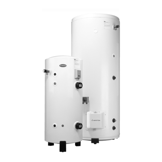
Ariston STI 210 INDIRECT Petunjuk Untuk Manual Instalasi - Halaman 5
Jelajahi secara online atau unduh pdf Petunjuk Untuk Manual Instalasi untuk Ketel uap Ariston STI 210 INDIRECT. Ariston STI 210 INDIRECT 24 halaman. Unvented hot water storage cylinders
Juga untuk Ariston STI 210 INDIRECT: Panduan Pengguna (16 halaman), Panduan Petunjuk Instalasi (20 halaman)

2.4
O
D
VERALL
IMENSIONS
ST 50-80-100
CONTRACT
STD 100-125-150-210
F
2.5
C
W
S
OLD
ATER
2.6
S
F
ITING AND
IXING
STORAGE
MODEL
CAPACITY
DIRECT RANGE
Wall Hung
ST 50
50 L
ST 80
75 L
ST 100
100 L
Floor Standing
CONTRACT STD 100
100 L
CONTRACT STD 125
125 L
CONTRACT STD 150
150 L
CONTRACT STD 210
200 L
CONTRACT STD 300
300 L
500 STD UK
495 L
INDIRECT RANGE
CONTRACT STI 125
125 L
CONTRACT STI 150
150 L
CONTRACT STI 210
200 L
CONTRACT STI 300
300 L
500 STI UK
495 L
COMFORT STI 125
125 L
COMFORT STI 150
150 L
COMFORT STI 210
200 L
CONTRACT
STI 125-150-210-300
F
It is important to ensure that the cold water main is capable of supplying the
UPPLY
increased demand which will be imposed on it. Hot and cold water are both
drawn off the same source of supply. Remember, there will not be a storage
tank to help compensate for variations in the demand on the system.
A minimum pressure of approximately 1.5 bar and 20 litres per minute is
required for satisfactory operation. 85% of UK dwellings have a mains
pressure above 2.0 bar.
N
OTE
The cylinder should be left packed until it is time to install. When unpacking
the appliance follow the guidelines within the packaging and take care not to
damage the temperature and pressure relief valve.
The cylinder may be installed at any convenient position, as it is connected
to the mains cold water supply, it is equally effective on any floor.
However, do not install the unit in premises which may be subject to
freezing. Ensure that the floor load bearing strength is adequate to take the
weight of the cylinder when full of water (see T
The ST50, ST80 and ST100 models are wall mounted. All other models are
free standing. These are supplied with feet which are attached to the heater
via self-tapping screws which are also supplied. All units must be installed in
the VERTICAL POSITION.
For maintenance purposes leave at least 500 mm free space in front of the
unit, for access to electrical components, immersion heater(s) and
magnesium anodes (where applicable).
COIL
UNITS PIPES SIZE
SURFACE
INLET OUTLET
m
2
1/2"
-
3/4"
-
3/4"
-
3/4"
-
3/4"
-
3/4"
-
3/4"
-
3/4"
-
1"
-
3/4"
0.75
3/4"
0.9
3/4"
0.9
3/4"
0.9
1"
1.5
3/4"
0.75
3/4"
0.9
3/4"
0.9
COMFORT
STI 125-150-210
F
: THE MAINS WATER SUPPLY MUST NOT EXCEED 16 BAR.
5
T
1
ABLE
DIMENSIONS IN MM
A
B
C
D
410
120
580
160
590
175
740
230
550
175
700
230
530
650
890
-
700
805
1045
-
840
965
1205
-
990
1280
1525
-
1215
1555
1790
-
1390
335
1870
-
700
805
1045
675
840
965
1205
815
990
1280
1525
815
1215
1555
1790
815
1390
335
1870
700
700
805
1045
675
840
965
1205
815
990
1280
1525
815
500 STD UK - 500 STI UK
1).
ABLE
WEIGHT
WHEN
E
F
FULL KG
475
460
77
475
460
115
575
560
141
-
505
129
-
505
158
-
505
190
-
505
245
-
560
385
-
714
630
-
505
166
-
505
201
-
505
256
-
560
395
-
714
641
-
505
169
-
505
203
-
505
258
F
795
