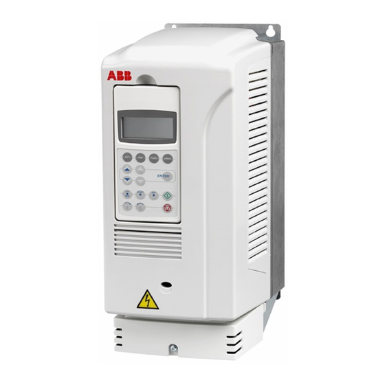
ABB ACS104 Manual - Halaman 12
Jelajahi secara online atau unduh pdf Manual untuk Unit Kontrol ABB ACS104. ABB ACS104 16 halaman. Converter modules with electrolytic dc capacitors in the dc link

12 Reforming the capacitors
3. Make this reforming circuit and connect it to the DC terminals of the converter module.
An external resistor is not needed if the DC power supply has an adjustable current
limiter.
Disconnect
U
U
x
x
4. Switch on the reforming circuit for the time defined in section
9.
Note: Limit the reforming current to max. 500 mA. If the DC power supply does not
have an adjustable current limiter, increase the voltage gradually from 0 to the full
scale value. Regulated DC power with active current limiting:
•
Output current: 0.5...1 A DC, max. 500 mA during reforming
•
Output voltage: adjustable 0...1000 V DC. An appropriate voltage during
reforming is 1.35...1.45·U
WARNING! The capacitors can get damaged if you use excessive DC voltage
during the reforming.
5. Switch off the reforming circuit.
6. Wait for 5 minutes (10 minutes for wind turbine converters) to let the converter DC
capacitors discharge.
7. Measure that the voltage of the DC terminals of the converter is close to 0 V.
8. Disconnect the reforming circuit from the converter.
DC power supply
DC Power supply
0.5 A ... 1 A 1000 VDC
SUPPLY
SUPPLY
UDC-
UNIT
W1
V1
U1
. U
denotes the nominal AC voltage of the converter.
x
x
0.5 A...1 A 1000 V DC
FREQUENCY
DRIVE MODULE
CONVERTER
R
= 100 Ohm / 500 W
INVERTER
INVERTER
UDC+
UNIT
W2
V2
U2
Reforming time
on page
