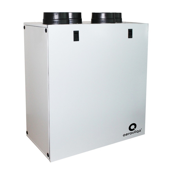
aerauliqa QR350MBP Panduan Instalasi - Halaman 6
Jelajahi secara online atau unduh pdf Panduan Instalasi untuk Kipas angin aerauliqa QR350MBP. aerauliqa QR350MBP 16 halaman. Heat recovery ventilation unit

5.g Connect the supplied condensation elbow(s) to the drainage hole(s) in the opening at the bottom of the unit: in case close and seal the non-used hole
with the 2 supplied plugs (one each side of the hole). Make sure of water and air tightness of all connections. It is necessary to use a U-bend (or similar)
in the condensation drainage pipe. The water drainage connections can be made either through the holes at the bottom side of the casing or through the
opening at the rear side of the casing.
5.h Connect the unit to the duct system. Make sure that all necessary accessories are used to create a functional ventilation solution.
5.i Connect the unit electrically according to point 5.4. Check that it starts up correctly.
5.4 Electric Connections
Make sure that the mains supply to the unit is disconnected before performing any installation, service, maintenance or electrical work!
The installation and service of the unit and complete ventilation system must be performed by an authorized installer and in accordance with local rules and
The unit must be earthed.
The QR350MBP is wired internally from factory.
Figures below show the wiring diagram.
5.j
Single speed operation
5.l
Two speed operation
5.n
Variable speed operation through external domotic
(BMS) system or ballast potentiometer
6
WARNING
WARNING
regulations.
SWITCH FOR BYPASS
ACTIVATION
5.k
Two speed operation
SWITCH FOR BYPASS
ACTIVATION
SWITCH FOR SPEED
2 SELECTION
5.m
Variable speed operation with CTRL-M remote manual controller
1-10V
BALLAST
+
-
SWITCH FOR BYPASS
ACTIVATION
5.o
Three speed operation with CTRL-S controller
SWITCH FOR BYPASS
ACTIVATION
TWO POSITION
SWITCH OR
REMOTE SENSOR
CTRL-M
+
U
-
SWITCH FOR BYPASS
ACTIVATION
S1
S2
S3
I
II
1
L
1
L
1
L
CTRL-S
