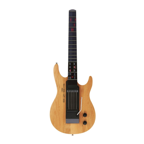
Yamaha EZ-EG Panduan Servis - Halaman 8
Jelajahi secara online atau unduh pdf Panduan Servis untuk Papan Ketik Elektronik Yamaha EZ-EG. Yamaha EZ-EG 34 halaman. Song chord chart
Juga untuk Yamaha EZ-EG: Panduan Pemilik (2 halaman), Panduan Singkat (2 halaman), Panduan Tambahan (3 halaman)

EZ-EG
5.
AM-3 Circuit Board
(Time required: about 15 minutes)
5-1
Remove the lower case assembly. (See procedure 1.)
5-2
Remove the DM circuit board. (See procedure 3.)
5-3
Remove the four (4) screws marked [130]. The vibrato arm
unit can then be removed. (Fig. 6)
5-4
Remove the two (2) screws marked [A50]. The base A can
then be removed from the vibrato arm unit. (Fig. 7)
5-5
Pull out the base B with AM-3 circuit board from the arm
holder in the direction shown by the arrow. (Fig. 8)
5-6
Remove the hexagonal nut marked [A]. The AM-3 circuit
board can then be removed. (Fig. 8)
[60]: Bind Head Tapping Screw-P 3.0X30 MFZN2BL (V8529300)
[110]: Bind Head Tapping Screw-P 3.0X8 MFZN2BL (EP630220)
• Vibrato Arm Unit
[A50]
[A50]
[A50]: Bind Head Tapping Screw-B 3.0X6 MFZN2BL (EP600230)
7.
MUTE 1/2 Circuit Board, MUTE 2/2 Circuit
Board, GS String
(Time required: about 20 minutes)
7-1
Remove the lower case assembly. (See procedure 1.)
7-2
Remove the DM circuit board. (See procedure 3.)
7-3
Remove the strings sensor unit. (See procedure 6.)
7-4
Remove the three (3) screws marked [180A]. The MUTE
1/2 circuit board can then be removed. (Fig. 9)
7-5
Remove the three (3) screws marked [180B]. The MUTE
2/2 circuit board can then be removed. (Fig. 9)
7-6
Remove the GS string with the bracket (Three each of the
1.0 and 1.2). The GS string can then be removed from the
bracket. (Fig. 9)
*
The brackets are comprised of the bracket 1.0 and the
bracket 1.2. The GS strings are comprised of the GS string
1.0 and the GS string 1.2. Take steps to prevent errors when
disassembling and assembling.
8
Vibrato arm unit
[130]
[60]
[60]
[130]
Base A
Base A
[A50]
[A50]
(Fig. 7)
6.
Strings Sensor Unit, Upper Case
(Time required: about 15 minutes)
6-1
Remove the lower case assembly. (See procedure 1.)
6-2
Remove the DM circuit board. (See procedure 3.)
6-3
Remove the four (4) screws marked [110]. The strings sen-
sor unit can then be removed. (Fig. 6)
6-4
Remove the vibrato arm unit. (See procedure 5-3.)
6-5
Remove the four (4) screws marked [60]. The upper case
can then be removed. (Fig. 6)
Strings sensor unit
[130]
[110]
[110]
[60]
[110]
Upper case
[130]: Bind Head Tapping Screw-P 3.0X8 MFZN2BL (EP630220)
(Fig. 6)
Base B
Base B
Arm holder
Arm holder
Arm holder
• Strings Sensor Unit
MUTE 2/2
[180B]
GS string 1.0
Bracket 1.0
GS string 1.0
[180]: Bind Head Tapping Screw-P 2.0X6 MFZN2BL (VG893800)
[60]
AM-3
[A]
[A]
(Fig. 8)
GS string 1.2
MUTE 1/2
The GS string 1.0 passes through the
bracket 1.0.
(The same applies to the bracket 1.2
and the GS string 1.2.)
(Fig. 9)
[180A]
