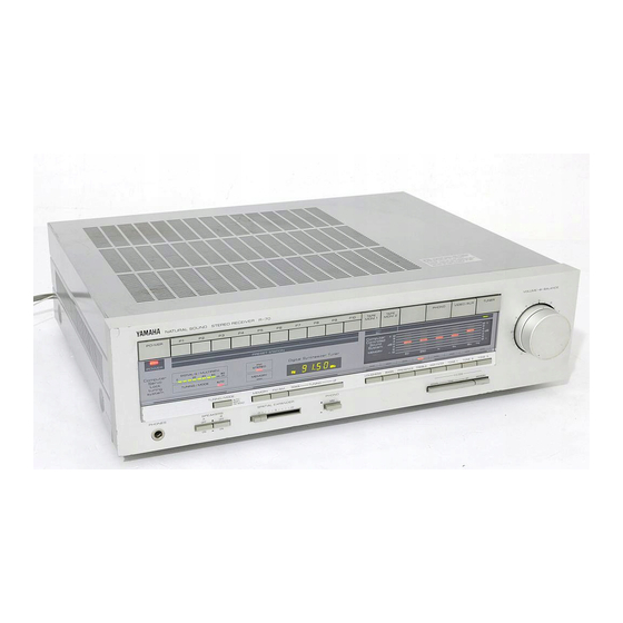
Yamaha R-70 Panduan Servis - Halaman 5
Jelajahi secara online atau unduh pdf Panduan Servis untuk Penerima Yamaha R-70. Yamaha R-70 21 halaman. Natural sound am/fm stereo synthesizer receiver
Juga untuk Yamaha R-70: Panduan Pemilik (12 halaman), Panduan Pemilik (12 halaman)

R-70
1
R-70M
ADJUSTMENTS
<CONFIRMATION
OF AUDIO SECTION>
Before adjustment
Note 1: After the power
switch
is pushed on, wait for 5 minutes
before
measuring, to be sure of the most stable operation.
Step
Confirmation
1
Power supply
voltage
2
Gain
4
DC offset
5
PHONO
amp
<TUNER
ADJUSTMENT>
•Before adjustment
Test point
+8
-8
+16
-16
+12
+5
+a
-a
IC414, across pin 4
and E (Leh)
across
pin 13
and
E (Reh)
IC414,
across pin
4
and
E (Leh)
across
pin 13 and
E (Reh)
PL,PR
Rating or standard
Adjustment method
+43V ±av
-43V ±av
Make sure that AC line voltage
+16V ± 2V
comes within
-16V ±
2V
Models AC line voltage
+12.5V
± 1V
+5.5V
± 0.5V
u.c
120V ± 10%
+av± 1v
G
220V ± 10%
-av±
1V
A. B
240V ± 10%
+10V±1V
Apply a 1kHz,100mV sine wave
signal to the points "BL" and "BR"
OV
±
70mV
Apply a 1 kHz, 2.5mV sine wave
signal to PHONO INPUT
+120mV ±
20mV
Apply a 1kHz, 160µV sine wave
signal to PHONO INPUT
Note 1) After the Power switch is pushed on, wait for 5
minutes before measuring, to be sure of the
most stable operation.
•Measuring instruments abbreviation
FM SG
: FM signal generate.
SSG
:
Stereo signal generator
AM SG : AM signal generator
Note 2) Adjust the OSC coil and I FT with a nonferrous
screw driver.
Note 3) Do not forget
to keep
the bottom cover on.
1. FM TUNER SECTION
OSC
: Oscilloscope
DIST. M: Distortion meter
FC
:
Frequency counter
ACVM
:
AC volt meter
Remark
No load
- - - -
PHONO
selector
set "MM"
PHONO
selector
set
"MC"
•Use 200Hz to 15kHz bandpass filter to measure the
REC OUT.
•Set the switches to the following positions.
•On step
1 and
2 connect the auxiliary
center
meter
(Ji00036 or
similar)
in series with the
resistor
1 Okr!
between TP1 (S OUT)
and
TP2 (NVcc).
Auxiliary center meter
Step
Adjustment
item
Connection
Instrument required
terminal
1
Discriminator
TP1 "'TP2
Aux i I iary center
balance adjust-
(Sout)(NVcc) meter
ment
2
Station
center set
300S1
FM
FM
SG
confirmation
ANT
~98MH' ±
1
kH'
l
70d8µ (75.2dBf)
MONO
1kHz
100% MOD
TP1 "'TP2
Auxiliary
center
(S
out)
(NV cc)
meter
3
Monaural
distor-
300S1 FM
FM SG
tion adjustment
ANT
[98MH'
±
1 kH'
j
70dBµ
(75.2dBf)
monaural 100Hz or
400Hz
REC OUT
100%
MOD
(TP6, TP7)
DIST. M. OSC BPF
INPUT . . . . . .
.
TUNER
Band Select .
.
. .
FM
TUNING/MODE
AUTO
VOLUME
. . .
. .
Min
Adjustment
Adjustment method
Rating or
Remarks
locations
standard
T102
Adjust so that the
(DISCRI
pointer of the auxil-
CENTER)
iary center meter points
to 0 at detuned point.
TUNING
SW
Confirm
that
the auxil-
~up
or DOWN iary center meter
deflects to 0 when
tuned to signal of
FM
SG
VC101
Reduce distortion to
Less than
Confirm that
(MONO DIST)
minimum
-64d8
all signal
Q
Signal
Q
indicators
light
I
4
