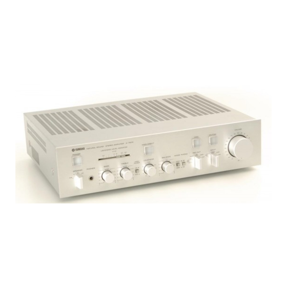
Yamaha A-760II Panduan Servis - Halaman 7
Jelajahi secara online atau unduh pdf Panduan Servis untuk Penguat Yamaha A-760II. Yamaha A-760II 29 halaman.

A-760
II
GENERAL A
JUSTMENTS
Before
ad
justm
ent
• Make su
re
t
hat t
he
AC line is ± 10%
• Wait 5 minut es
aft
er power-on to stabilize amplifier operation
Test
St
ep
Ad just
ment
Conditions
Loeation
Test
Po
int
Value
Equipment
:
Main B+"B-
Between chassis ground
Digital
Main board 1
voltage ad-
No load
and P1 terminal of pr i-
47.5±O.3V
voltmeter
1
VR303
justment
mary board
(test er)
Between P1 and TP3 of the primary board
1.2V±O.1V
Photo
coup-
Minimum
volume,
(if out of ranqe, turn to VR501 and VR303
(2.0V±0.1V
same as
2
ler
current
no load
and adjust B+, B- and P1 - TP3
=FEMKO,
above
check*
for rated voltages)
DEMKO)
Main
board 1.
Idling
TP3 - TP4 (L),
sam
e
as
3
Minimum volume
VR301 (L ch) ,
6.6
:g
mV
adjustment
TP1 - TP2 (R)
abo
ve
VR302 (R ch)
Output off
-
L. R within
same as
4
Minimum volume
Speaker terminals
set ch
eck
o
± 30 mV
above
* It is not necessary to check the
photo-coupler
current of step 2 except when replacing the
photo-coupler,
Also
,
pe rfo rm steps 1 and 2 simultaneously (with two digital voltmeters).
A
DJUSTMENT LOCAT
ION
DIAGRAM
Main c. board 1
D
VR301 (L
)
VR3
0 2lRl
TP3
@
@
Prim ary
c. board 1
c
00
TPI
TP4
c
c
TP
2
c
VR501
o
0
0501
0
10
TR501
TP5
o
D
o
•
TP
7
rp6
c
o
PlmTP3
FRONT
Primary c. board 2
-
- - - - - -
---------
-
-
- - - - - - ------------ - -6
