Directed Xpresskit DBALL2 Panduan Instalasi - Halaman 3

Jelajahi secara online atau unduh pdf Panduan Instalasi untuk Dengan kunci Directed Xpresskit DBALL2. Directed Xpresskit DBALL2 18 halaman. Ford5 remote start ready (rsr) installation
Juga untuk Directed Xpresskit DBALL2: Panduan Instalasi (12 halaman), Panduan Instalasi (19 halaman), Panduan Instalasi (18 halaman), Manual (14 halaman), Panduan Instalasi (13 halaman), Panduan Instalasi (14 halaman), Panduan Instalasi (19 halaman), Panduan Instalasi (16 halaman), Panduan Instalasi (20 halaman), Panduan Instalasi (15 halaman), Panduan Instalasi dan Referensi Cepat (16 halaman), Panduan Instalasi (16 halaman), Panduan Instalasi (18 halaman), Panduan Instalasi (16 halaman), Manual (19 halaman)
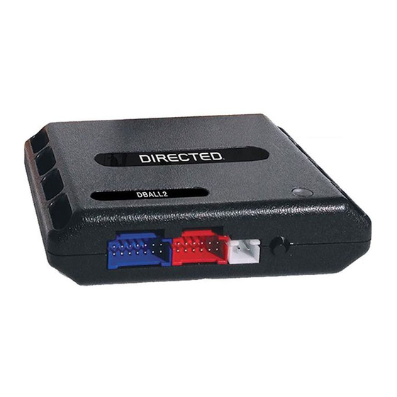
Directed Xpresskit DBALL2 Panduan Instalasi
Platform: DBALL2
Firmware:
HYUNDAI9 Remote Start Ready (RSR) Installation
Installation Type 1
Important!
The Hood Pin and Remote Start Safety Override Switch are mandatory safety devices, but are NOT supplied with the DBALL.
87
86
87a
30
Fuse
30A
Smart Key Ign. Interrupt (conn. side): Orange/Red: 10
Smart Key Ign. Interrupt (veh.side): Yellow/Red: 11
31
1
(+) 12V:
White,
32
22
12
2
pin 31
33
23
3
13
34
24
14
4
35
25
15
5
36
26
21
16
6
37
27
17
7
38
28
18
8
39
29
19
9
40
30
20
10
I/P-A Fusebox/Smart Junction Box
41 11
(White conn. front of
fusebox/smart junction box)
With the exception of the OBDII Diagnostic connector, all adapters are displayed from the wire side (unless specified otherwise).
EMS COM:
Blue, pin 20
(+)Starter:
Red/Black,
pin 31
86
87
85
87a
30
85
(+) Ignition: Blue, pin 36
(+) Accessory: Green, pin 28
C-CAN High: Green, pin 6
C-CAN Low: Orange, pin 14
HS CAN High: Tan/Black: 3
HS CAN Low: Tan: 4
FT CAN High: Orange/Green: 5
FT CAN Low: Orange/Brown: 6
(+) 12V: Red: 13
(-) Ground: Black: 14
(-) Ignition Output: Black/White: 1
(+) Accessory Output: Gray: 6
(+) Starter Output: Gray/Black: 7
(MUX) Parking Lights Output: Violet/Brown: 9
EMS COM: Orange/Black: 11
(MUX) Parking Lights:
Yellow, pin 14
1
2
3
4
5
6
7
8
Headlight/Wiper switch
9
10
11
12
13
14
15
16
(Black conn. at steering column)
1
3
37 29
22 18
10
38 30
19
23
11
39
31
20
12
1
40
2
41
3
42
32
4
13
4
43
33
5
14
5
44
34
6
15
6
45
35
7
16
7
46
MC11 Junction
8
47
9
(Gray conn. at driver kick panel)
48
36 28
21
17
Green/Black, pin 3
Diagnostic Connector
1
8
OBDII (connector side view)
9
16
RF
DBALL2
Prog. Button
LED
Smart Key Ignition Interrupt
Green, pin 6
B-CAN Low:
Blue/Black, pin 4
1
3 4
5
6
7 8
2
13 14 15 16
11 12
B-CAN High:
I/P-F Fusebox/Smart Junction Box
(White conn. rear of
fusebox/Smart Junction Box)
Note: Hood pin only required
on vehicles not equipped
with a factory hood pin.
Hood Pin
Remote Start Safety
Override Switch
6: White/Black,(-) Hood
You can connect to either a XL202
RFTD OR a SmartStart module.
Refer to the SmartStart/XL202
Installation Notes for more information.
© 2015 Directed. All rights reserved.
Rev.: 20161206
Page 3
Required for
CUT
vehicle takeover
10
9
17
18