Directed Electronics IntelliGuard 7000 Panduan Instalasi - Halaman 4
Jelajahi secara online atau unduh pdf Panduan Instalasi untuk Alarm Mobil Directed Electronics IntelliGuard 7000. Directed Electronics IntelliGuard 7000 16 halaman. Car security system intelliguard 7000

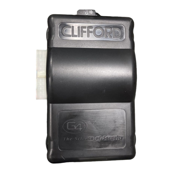
Control Unit and Extended Range Receiver
The IntelliGuard 7000 con trol unit must be in stalled in side the ve hi cle. Un der no cir cum stances should the unit
be in stalled un der the hood or other simi larly hos tile en vi ron ment.
1. Select an area behind the dash to mount the control unit using wire ties, but do not permanently affix it until all wiring and testing
is complete.
2. Plug the extended range receiver in to the control unit. Mount the extended range receiver away from the control unit and run
the antenna either up the window pillar and affix it to the windshield, or under the dash, away from metal. The position and
location of the receiver will effect remote control range. Do not fold the excess cable or antenna wire. Do not make hard, sharp
bends.
Door Trigger/Interior Light Supply
Please refer to the Door Trigger & Interior Light Supply section in this binder for information on polarity testing and connections.
Central Door Locking System
Please refer to the Door Locks section in this binder for information on circuit types and connections.
LED Status Indicator
Select a prominent location on the dash or console visible through all windows. Discuss placement with the owner.
1. Verify there is adequate space to accommodate the LED, then drill a 5/16" (8mm) hole and route the wires through it.
2. Mate the LED connectors to the VIOLET and BLACK wire connectors as shown in the diagram on page 7.
3. Press the LED into place.
PlainView 2 Coded Valet/Programming Switch
1. Discuss placement of the switch with the vehicle owner and avoid placing the switch where it can be pressed accidentally.
2. Verify there is adequate space behind the selected location to accommodate the switch.
3. Drill a 5/16" (8mm) mounting hole, then insert the wires through the hole.
4. Mate the switch's locking connectors to the WHITE and BLACK locking connector.
5. Remove the adhesive backing and press the switch into place.
Trunk Trigger
Vehicles with a ground-switching trunk light will interface directly with the IntelliGuard 7000 (on positive switching Rolls-Royce vehicles,
use a relay to invert polarity). The switch may be located in or near the trunk latch or at the trunk light. If a switch cannot be
located, you must add a pin switch in a location away from water channels.
NOTE: If the ve hi cle has a dash board trunk ajar in di ca tor, in stall a 1- amp di ode be tween the light and switch
with the di ode band point ing to ward the switch.
1. Connect the GRAY/YELLOW wire to the trunk switch (between the diode and switch if you added a diode).
Brake Switch
The brake switch connection is required for the operation of the IntelliGuard 7000's anti-carjacking electronics.
1. Turn the ignition to the "ON" position and press the brake pedal to verify that the brake lights are operational.
2. Find the one wire that carries +12V when the brake pedal is pressed, then connect the BLUE/WHITE wire to this wire.
Parking Lights
See the Door Trigger & Parking Lights section in this binder.
4
Passenger Compartment Connections
In tel liGuard 7000/199
