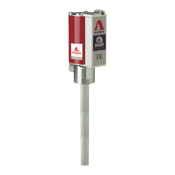
Alemite 9911-J Panduan Servis Pemilik - Halaman 6
Jelajahi secara online atau unduh pdf Panduan Servis Pemilik untuk Pompa Air Alemite 9911-J. Alemite 9911-J 16 halaman. 9911 series and 9950 series high pressure stripped pump

27 Place a bar or other suitable tool in the
holes of the primer body for leverage.
28 Tighten sufficiently to properly crush all
gaskets.
CAUTION
Use care not to switch Washers (3 and 7).
Component damage can occur.
29 Install washer (7) [brass color] and
o-ring (6) onto the rod.
30 Install quad-ring (5) onto air piston (4).
31 Place the air piston (observe this side up)
on top of the rod.
32 Install washer (3) [silver color] and
nut (2) that secures theair piston to the
rod.Tighten the nut securely.
NOTE
Place an appropriate size punch or other
suitable tool into the hole of the rod
(† fig. 2-A).
Attach air motor to pump
tube
1 Clamp the pump at the flats of body (10)
securely in a soft jaw vise.
2 Install the bottom cap onto the body.
3 Install o-ring (8) onto the upper groove of
the body.
CAUTION
Install the cylinder with care. Damage to
quad-ring (5) and/or 0-ring (8) can occur.
NOTE
Angle the cylinder onto the quad-ring.
4 Install the cylinder over the body's o-ring
and seat it properly onto the bottom cap.
5 Install thetop cap onto the cylinder.
Use care passing the o-ring.
6 Install keeper (11) into the groove of the
body. Make sure the hole aligns with
carriage bolt (1c).
7 Install one carriage boitthroughtheairmo-
torandthrough the keeper.
8 Install flange nut (1d). Do not tighten the
flange nut at this time.
9 Repeat procedural steps 7 and 8 for the
additional keepers and carriage bolts.
CAUTION
Do not overtighten flange nuts (1d). Compo-
nent damage can occur.
10 Torque each flange nut in an alternate
pattern from 60 to 70 in.lbf.
(6.8 to 7.9 Nm).
11 Install screw (1b) into the top cap.
Tighten the screw to 50 in.lbf (5.6 Nm).
12 "Snap" cover (1a) onto the cylinder.
Bench test and
operation
1 Slowly supply air pressure [recom-
mended minimum of 25 psi (1.7 bars)] to
the pump's motor. The pump assembly
should cycle. If the pump assembly does
not cycle, refer to the troubleshooting
chart for details.)
With air pressure at zero:
2 Connect a product hose to the pump's
material outlet. Direct the hose into an
appropriate collection container.
3 Place the pump in grease.
4 Slowly supply air pressure to the pump's
motor.
WARNING
Should leakage occur anywhere within the
system, disconnect air to the motor. Personal
injury can occur.
5 Allow the pump to cycle slowly until the
grease is free of air. If the pump assem-
bly does not prime, refer to the trouble-
shooting chart for details).
With air pressure at zero:
6 Attach a control valve to the outlet hose
of the pump. Make sure the nozzle on
the control valve is open.
7 Slowly supply air pressure to the pump's
motor.
8 Allow the pump to cycle slowly until the
grease is once again free of air.
9 Set the air pressure to the normal oper-
ating pressure.
10 Operate the control valve into a
container.
11 Shut off the control valve.
6
12 Visually inspect the pump for external
leaks. The pump should not cycle more
than once or twice in one hour. If the
pump does not stall, refer to the trouble-
shooting chart for details.
13 Check the motor for air leakage. If the
motor leaks, refer to the air motor
service guide for details.
Installation
Additional items that should be incorporated
into the air piping systems are listed in
table 5, below.
Air line components
Part numbe
Description
5604-2
Moisture separator
7604-B
Regulator and gauge
Table 5
