Clarke USE240 Petunjuk Pengoperasian & Pemeliharaan - Halaman 2
Jelajahi secara online atau unduh pdf Petunjuk Pengoperasian & Pemeliharaan untuk Pompa Air Clarke USE240. Clarke USE240 4 halaman. Submersible water pump

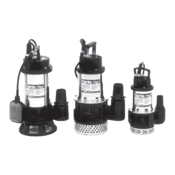
Thank you for purchasing this Clarke HSE Submersible Pump.
These highly efficient pumps are designed for pumping clean water, or water
containing sand or solids in suspension, depending upon the model (please see
below), and are ideally suited for draining ponds, pools, building excavations
etc.Water temperature must not exceed 35 C.
Before attempting to operate your pump, please read this instruction manual
thoroughly and follow all directions carefully. This is for your own safety and that
of others around you, and to help you achieve long and trouble free service from
your pump.
GUARANTEE
This product is guaranteed against faults in manufacture for 12 months from
purchase date. Keep your receipt as proof of purchase.This guarantee is invalid if
the product has been abused or tampered with in any way, or not used for the
purpose for which it is intended. The reason for return must be clearly stated. This
guarantee does not affect your statutory rights.
SAFETY PRECAUTIONS
1. These pumps are designed to pump WATER ONLY. Never use for pumping
flammable liquids or chemicals.
2. Never run the pump dry
3. An approved Residual Current Device (RCD) must be used when pumping
from ponds or swimming pools.
4. Your submersible pump may only be used for pumping water from a swim
ming pool when there is no person or animal in the pool.
5. Always disconnect the pump from the electrical supply before placing it
into, or removing it from the water, and before any cleaning or maintenance
of the pump.
6. Always use the moulded handle, with a rope or cord attached if necessary,
when lifting the pump. Do not lift the pump by the mains cable, or, where
fitted, the float switch cables.
7. DO NOT run the pump with the body exposed for longer than 10 minutes.
8. DO NOT install the pump on sand, or ground which is likely to shift.
9. Do not use the pump if the water is liable to freeze, as this can cause dam
age to the pump. Remove the pump from the water and store it in a frost
free location.
10. If the pump is to be used where there may be silt or mud (for example,
garden ponds), keep the pump clear of any sediment by standing it on a
platform or brick.
11. Always disconnect the pump from the mains supply before placing it into or
removing it from water, and before any cleaning or maintenance of the
pump.
2
PARTS LIST & DIAGRAM
No. Description
Part No.
1
Strainer
HG400A01
2
Strainer Packing
HG400A02
3
Impeller
HG400A13
4
Pump Casing
HG400A04
5
Oil Seal
HG400A05
6
Oil Cover
HG400A06
7
Oil Cover Packing
HG400A07
8
Mechanical Seal
HG400A08
9
Motor Casing Pkg
HG400A09
10
Lower Bearing
HG400A10
11
Motor Casing
HG400A11
12
Rotor Shaft
HG400A12
13
Stator Coil
HG400A13
14
Centrifugal Switch
HG400A14
15
Thermal Overload
HG400A15
16
Centrifugal Plate
HG400A16
17
Upper Bearing
HG400A17
18
Motor Casing Pkg
HG400A18
19
Inside Cover
HG400A19
20
Head Cover Pkg.
HG400A20
21
Capacitor
HG400A21
22
Cable Gland
HG400A22
23
Gland Packing
HG400A23
24
Power Cable
HG400A24
25
Handle
HG400A25
26
Outlet Discharge.
HG400A26
SPECIFICATIONS
Model No.
Outlet Dia. (in/mm)
Motor Output (Watts)
Head Max. (M)
Capacity Max. (L/min)
Head Continuous (M)
Capacity at Cont. Head (L/min)
Dimensions LxWxH (mm)
180x130x310
Weight (kg)
Cable (Mxmm
2
)
HSEC 400A
HSE 120
HSE 240
HSE 120A
HSE 240A
HSEC 400A
HSE 200A
HSE 250A
1¼/32
2/50
150
400
7
12
120
240
4
8
80
130
240x180x430
230x170x420
7
15
10x1.00
10x1.00
10x1.00
7
2/50
400
8
240
5.5
100
18
