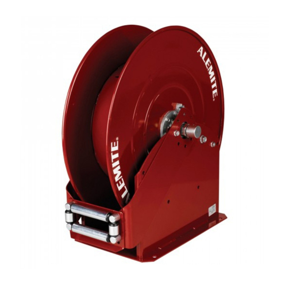
Alemite 7340 Panduan Servis - Halaman 5
Jelajahi secara online atau unduh pdf Panduan Servis untuk Kabel dan konektor Alemite 7340. Alemite 7340 16 halaman. High-capacity
Juga untuk Alemite 7340: Panduan Servis (12 halaman)

Sheave assembly
19 Remove the sheave assembly (with
attached components) from the base
assembly.
20 Remove the shaft (with attached compo-
nents) from ratchet (35).
21 Remove 90 ° union (6) from the shaft [or
bushing (7)] as required.
21.1 Remove the bushing from the
shaft as required.
22 Remove screws (5) and nuts (1) that
secure the ratchet to the sheave
assembly.
22.1 Remove the ratchet from the
sheave assembly.
23 Remove screws (5) and nuts (1) that
secure the shaft and flange assembly to
the sheave assembly.
23.1 Remove the shaft and flange
assembly from the sheave
assembly.
Base assembly
Pawl and shaft assembly
24 Remove nut (1) that secures spring
post (23) to the base assembly.
24.1 Remove the spring post from the
base assembly.
25 Remove extension spring (24) from pawl
and shaft assembly (25).
25.1 Remove the extension spring from
the spring post.
26 Remove screw (32) that secures the pawl
and shaft assembly to the base
assembly.
26.1 Remove the pawl and shaft
assembly from the base assembly.
27 Remove bolts (31 and 30), and
washers (29) from the base assembly as
required.
Components lubricated in lithium grease
Item
Description
22
O-ring,
1
/
in (6.4 mm) ID x
4
24
Hooks of pawl spring
Clean and inspect
NOTE
Use the appropriate repair kit for
replacement parts. Make sure all the
components are included in the kit
before discarding used parts.
Clean all metal parts in a modified petrole-
um-based solvent. The solvent should be
environmentally safe.
Make sure to remove the old sealant from
the threads of all components.
3
/
in (9.5 mm) OD
8
Assembly
NOTE
Prior to assembly, certain components
require lubrication. Refer to Table 2 for
details.
Base assembly
NOTE
Refer to figs. 2, page 7 and
IPB1, page 13 for component
identification on all of the assembly
procedures.
Pawl and shaft assembly
1
NOTE
Make sure to attach the pawl and shaft
assembly to the upright without the
captive nuts.
2 Secure the pawl and shaft assembly to
3 Install extension spring (24) into the eye
4 Secure the spring post to the base
Item
Description
35
Teeth on ratchet
38
Seal,
1
/
in (12.7 mm) ID x
2
43
Seal,
/
in (9.5 mm) ID x
3
8
5
Apply threadlocker to the threads of
pawl and shaft assembly (25).
base assembly (33) with screw (32).
2.1 Tighten the screw to 42 - 48 ft.lbf
(57 - 65 nm).
on the pawl and onto spring post (23).
assembly with nut (1).
4.1 Refer to fig. IPB1, page 13 for the
proper hole location.
4.2 Tighten the nut securely.
3
/
in (19 mm) OD
4
/
in (19 mm) OD
3
4
Table 2
