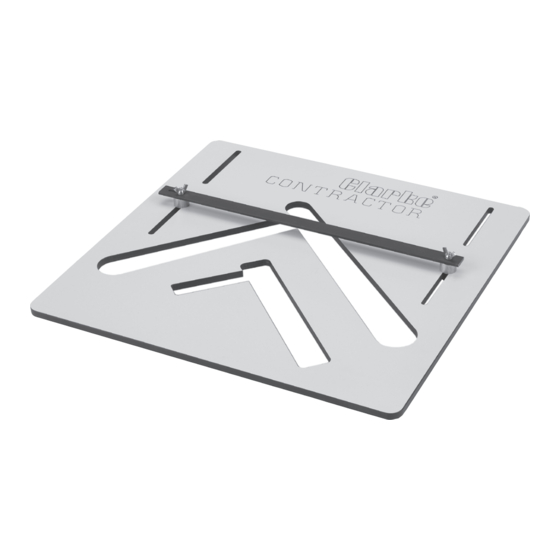
Clarke CONTRACTOR 6462120 Panduan Petunjuk Pengoperasian & Pemeliharaan - Halaman 9
Jelajahi secara online atau unduh pdf Panduan Petunjuk Pengoperasian & Pemeliharaan untuk Peralatan Clarke CONTRACTOR 6462120. Clarke CONTRACTOR 6462120 12 halaman. Stair jig

13. Attach the correct nosing bush and cutter size to the router, set the plunge depth
to 12mm (refer to tabIe on page 7 for correct guide bush and Cutter).
14. Proceed to cut out the tread and riser
housing using the sequence shown in
diagram (right). Always refer to router
manufacturers instructions before
commencing.
Pitch Angle Line
string. The distance between each movement of the Jig is equal to the length of the
pitch angle line (See diagram above), refer back to page 6 when steps were followed
to calculate the pitch angle line and the length measured. The angle of the pitch is
maintained by the sliding bar mechanism.
The procedure to follow is to mark a line along the margin where the right hand side of
the stair jig crosses. From this point, measure the length of the pitch angle line along the
margin and mark this point. This is the place at which to position the right hand side of the
stair jig for the next succession. Please ensure before re-clamping the jig, the sliding bar is
pushed firmly against the top edge of the string.
Repeat this procedure until the required number of rise and going recesses have been
cut.
IMPORTANT: whenever repositioning the jig, always ensure the spacers are pushed up
firmly against the edge of the string before clamping in position.
The edge of bush has to be flat with inside edge of jig
to ensure correct nosing and gap thickness for tread.
Ensure the long side of the guide
bush is flat against the side of the aperture to ensure a
correct size nose and width of cut for the tread to fit
comfortably.
Next jig position
15. You should now have completed the
first going and riser recess on the first
string. To complete the succession of
goings and risers along this string, the jig
must be moved sequentially along the
-8-
