Clarke CONTRACTOR 6462122 Panduan Petunjuk Pengoperasian & Pemeliharaan - Halaman 6
Jelajahi secara online atau unduh pdf Panduan Petunjuk Pengoperasian & Pemeliharaan untuk Peralatan Clarke CONTRACTOR 6462122. Clarke CONTRACTOR 6462122 8 halaman. Lock jig

Using the Jig
Depending on the size of lock to be fitted etc, all that is required is to mark on the door
edge the centre line of the lock position. As a general guideline the centre line would
normally be 1 metre from the bottom of the door.
Once the lock position is determined, mark the centre
line across the door edge (Fig. 5). This mark is used to
position the jig in the correct place for routing.
Loosen both wing screws and turn levers fully
anticlockwise.
Place the jig on the edge of the door, slide into position
so that the centre line on the jig lines up with the marked
centre line on the door edge (Fig. 6).
Turn levers fully clockwise and secure in position by
tightening both wing screws (Fig. 6a), DO NOT overtighten.
Check Jig is in the correct position, once satisfied, carefully
secure the jig to the door edge using suitable woodscews
in the securing holes (3mm ø) top and bottom of the jig.
Securing Holes (3mm ø)
Fig. 6
Securing Holes (3mm ø)
-5-
Before continuing, check that the
centre line on the door is still lined
up with the centre mark on the
nesting plate, if not adjust until it
does.
Fig. 6a
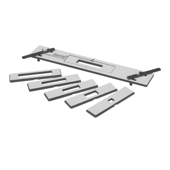
NOTE: when selecting inserts, take
into account the aperture will cut
approx 1.65mm smaller all round. If
in doubt test on a piece of scrap first.
Fig. 5
Centre Line
Dotted line showing
lock position
